


Filter by
Product Family
Switching Voltage
Electrical Connection
Switch Designation
Switch Action
Switch Starting Position
Wire Connection

Number of Terminals
Maximum Temperature
Operating Temperature
Housing Material
Export Control Classification Number (ECCN)
DFARS Specialty Metals
Harsh Environment Snap-Acting Switches
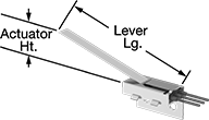 | 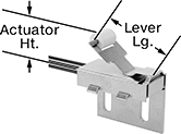 |
Style A | Style B |
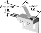 | 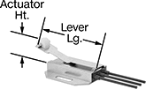 |
Style C | Style D |
 | |
Style E |
Open and close circuits in a snap—even in harsh conditions. With a rubber-encased housing and stainless steel bracket, these switches handle high vibrations and resist corrosion. They’re rated IP68 for protection from dust and temporary submersion. Because they open and close circuits faster than other switches—reducing the time that contacts are near one another—they prevent contacts from sticking. They also minimize the chance of arcing, so electricity won’t jump across contacts. They’re often used as door-open indicators on enclosures or as an internal component in limit, pressure, and temperature switches.
Lever Actuator Style—Lever actuator switches can be pushed down by front-to-back movement, so they can be activated with pressure anywhere along their length.
Roller Lever Actuator Style—Roller lever actuator switches activate when parts glide front-to-back across their actuation surface. They produce less friction than standard levers, which prevents wear and tear over time.
Simulated Roller Lever Actuator Style—Simulated roller lever actuator switches have a curved arm that can be pressed down for actuation by forward, backward, and repeated back-and-forth movement.
Dual Switch Roller Lever Actuator Style—Dual switch roller lever actuator switches actuate two SPDT switches simultaneously, giving you the equivalent of a DPDT switch. A roller at the end of the arm reduces friction and wear from parts moving across their actuation surface.
Wire Leads | Housing | ||||||||||||||||||
|---|---|---|---|---|---|---|---|---|---|---|---|---|---|---|---|---|---|---|---|
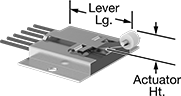
Style | No. of Circuits Controlled | Switch Starting Position | Switch Action | Switch Designation | Switching Current @ Voltage | Max. Voltage | Operating Temp. Range, ° F | Actuator Ht. | Wire Connection | No. of | Lg. | Lg. | Ht. | Dp. | Lever Lg. | Each | |||
Side Mount | |||||||||||||||||||
Lever Actuator Style | |||||||||||||||||||
| A | 1 | 1 Off | Momentary | SPST-NO | 5 amp @ 120V AC 5 amp @ 28V DC | 120V AC 28V DC | -40 to 185 | 1.04" | Wire Leads | 2 | 24" | 0.86" | 1.13" | 1.75" | 4.5" | 7287K102 | 0000000 | ||
| A | 1 | 1 Off or 1 On | Momentary | SPDT | 5 amp @ 120V AC 5 amp @ 28V DC | 120V AC 28V DC | -40 to 185 | 1.04" | Wire Leads | 3 | 24" | 0.86" | 1.13" | 1.75" | 4.5" | 7287K11 | 00000 | ||
Roller Lever Actuator Style | |||||||||||||||||||
| B | 1 | 1 Off | Momentary | SPST-NO | 5 amp @ 120V AC 5 amp @ 28V DC | 120V AC 28V DC | -40 to 185 | 0.81" | Wire Leads | 2 | 24" | 1" | 1.42" | 1.75" | 1.4" | 7287K103 | 000000 | ||
| B | 1 | 1 Off or 1 On | Momentary | SPDT | 5 amp @ 120V AC 5 amp @ 28V DC | 120V AC 28V DC | -40 to 185 | 0.81" | Wire Leads | 3 | 24" | 1" | 1.42" | 1.75" | 1.4" | 7287K12 | 00000 | ||
Simulated Roller Lever Actuator Style | |||||||||||||||||||
| C | 1 | 1 Off | Momentary | SPST-NO | 5 amp @ 120V AC 5 amp @ 28V DC | 120V AC 28V DC | -40 to 185 | 0.81" | Wire Leads | 2 | 24" | 1" | 1.42" | 1.75" | 1.3" | 7287K101 | 000000 | ||
| C | 1 | 1 Off or 1 On | Momentary | SPDT | 5 amp @ 120V AC 5 amp @ 28V DC | 120V AC 28V DC | -40 to 185 | 0.81" | Wire Leads | 3 | 24" | 1" | 1.42" | 1.75" | 1.3" | 7287K13 | 00000 | ||
Bottom Mount | |||||||||||||||||||
Roller Lever Actuator Style | |||||||||||||||||||
| D | 1 | 1 Off | Momentary | SPST-NO | 5 amp @ 120V AC 5 amp @ 28V DC | 120V AC 28V DC | -40 to 185 | 0.61" | Wire Leads | 2 | 24" | 1.75" | 0.34" | 1.75" | 2.2" | 7287K104 | 000000 | ||
| D | 1 | 1 Off or 1 On | Momentary | SPDT | 5 amp @ 120V AC 5 amp @ 28V DC | 120V AC 28V DC | -40 to 185 | 0.61" | Wire Leads | 3 | 24" | 1.75" | 0.34" | 1.75" | 2.2" | 7303K11 | 00000 | ||
Dual Switch Roller Lever Actuator Style | |||||||||||||||||||
| E | 2 | 1 Off or 1 On | Momentary | SPDT | 5 amp @ 120V AC 5 amp @ 28V DC | 120V AC 28V DC | -40 to 185 | 0.6" | Wire Leads | 6 | 24" | 2.5" | 1.25" | 1.75" | 2.3" | 7303K12 | 000000 | ||
Heavy Duty Limit Switches
 |  |  |
Housing | ||||||||||||||||||||
|---|---|---|---|---|---|---|---|---|---|---|---|---|---|---|---|---|---|---|---|---|
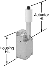
Actuation Direction | No. of Circuits Controlled | Switch Starting Position | Switch Action | Switch Designation | Switching Current @ Voltage | Max. Voltage | Actuation Torque, in·ozf | Operating Temp. Range, ° F | Actuator Ht. | For Max. Cable OD | No. of Terminals | Lg. | Ht. | Dp. | Housing Material | Enclosure Rating | Each | |||
Roller Lever Actuator | ||||||||||||||||||||
Screw-Terminal Wire Connection | ||||||||||||||||||||
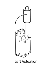
| Left | 2 | 2 Off | Momentary | DPST-NO | 20 amp @ 120V AC, 5 amp @ 120V DC | 600V AC 600V DC | 150 | -10 to 185 | 5.7" | 0.5" | 4 | 2.3" | 5" | 3.4" | Aluminum | NEMA 4, NEMA 13, IP67 | 7904N22 | 0000000 | ||
| Left | 2 | 2 On | Momentary | DPST-NC | 20 amp @ 120V AC, 5 amp @ 120V DC | 600V AC 600V DC | 150 | -10 to 185 | 5.7" | 0.5" | 4 | 2.3" | 5" | 3.4" | Aluminum | NEMA 4, NEMA 13, IP67 | 7904N24 | 000000 | ||
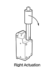
| Right | 2 | 2 Off | Momentary | DPST-NO | 20 amp @ 120V AC, 5 amp @ 120V DC | 600V AC 600V DC | 150 | -10 to 185 | 5.7" | 0.5" | 4 | 2.3" | 5" | 2" | Aluminum | NEMA 4, NEMA 13, IP67 | 7904N21 | 000000 | ||
| Right | 2 | 2 On | Momentary | DPST-NC | 20 amp @ 120V AC, 5 amp @ 120V DC | 600V AC 600V DC | 150 | -10 to 185 | 5.7" | 0.5" | 4 | 2.3" | 5" | 2" | Aluminum | NEMA 4, NEMA 13, IP67 | 7904N23 | 000000 | ||
| Right | 2 | 1 Off and 1 On | Momentary | DPST-1NO/1NC | 20 amp @ 120V AC, 5 amp @ 120V DC | 600V AC 600V DC | 150 | -10 to 185 | 5.7" | 0.5" | 4 | 2.3" | 5" | 2" | Aluminum | NEMA 4, NEMA 13, IP67 | 7904N25 | 000000 | ||
