


Filter by

Material
Mounting Location
Overall Length

Draw Latch Type
Latching Distance

Weight Capacity
Overall Width
Width
Length
Finish
DFARS Specialty Metals
Export Control Classification Number (ECCN)
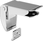
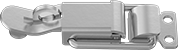
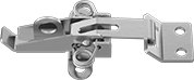
Corner-Mount Draw Latches
 |  |  |  |
Style A | Style B | Style C | Style D |
 |  |  | |
Style E | Style F | Style G |
Overall | Mounting | ||||||||||||
|---|---|---|---|---|---|---|---|---|---|---|---|---|---|
Style | Material | Appearance | Latching Distance | Lg. | Wd. | Projection | Wt. Cap. | Fasteners Included | Screw Size | Each | |||
Screw On | |||||||||||||
| A | Zinc-Plated Steel | Dull | 1" | 3 3/16" | 1 9/16" | 1 1/16" | 310 lb. | No | M5 | 4432N111 | 000000 | ||
| B | 304 Stainless Steel | Polished | 13/16" | 2 1/8" | 15/16" | 7/8" | 155 lb. | No | M4 | 4432N112 | 00000 | ||
| C | 304 Stainless Steel | Polished | 13/16" | 2 1/8" | 15/16" | 7/8" | 155 lb. | No | M4 | 4432N113 | 00000 | ||
| D | 304 Stainless Steel | Polished | 1 7/16" | 5" | 2 3/16" | 1 13/16" | 895 lb. | No | M6 | 4432N116 | 00000 | ||
| D | 304 Stainless Steel | Polished | 2 3/8" | 6 15/16" | 2 5/8" | 2 3/16" | 1,010 lb. | No | M6 | 4432N115 | 00000 | ||
| D | 304 Stainless Steel | Polished | 2 3/8" | 9" | 2 5/8" | 2 3/8" | 1,010 lb. | No | M6 | 4432N114 | 00000 | ||
| E | 304 Stainless Steel | Polished | 11/16" | 2 1/8" | 1 1/16" | 7/16" | Not Rated | No | M3 | 4432N122 | 00000 | ||
| E | 304 Stainless Steel | Polished | 15/16" | 2 5/8" | 1 5/16" | 1/2" | Not Rated | No | M4 | 4432N121 | 00000 | ||
| E | 304 Stainless Steel | Polished | 1 5/16" | 3 1/4" | 1 5/8" | 9/16" | 115 lb. | No | M4 | 4432N119 | 00000 | ||
| F | 304 Stainless Steel | Polished | 2 1/16" | 2 7/16" | 1 1/8" | 3/4" | 75 lb. | No | M4 | 4432N118 | 00000 | ||
| G | 304 Stainless Steel | Polished | 1 7/8" | 2 1/4" | 1 13/16" | 1/2" | 25 lb. | No | M4 | 4432N117 | 00000 | ||
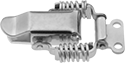
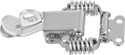
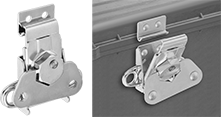
Tight-Hold Draw Latches with Safety Catch
 |  |  |
Style A | Style B | Replacement Latch Strike Plates |
Latches | Replacement Latch Strike Plates | ||||||||||||||
|---|---|---|---|---|---|---|---|---|---|---|---|---|---|---|---|
Overall | Mounting | ||||||||||||||
Style | Material | Appearance | Latching Distance | Lg. | Wd. | Projection | Wt. Cap. | Fasteners Included | Screw Size | Each | Each | ||||
Screw On | |||||||||||||||
| A | 300 Series Stainless Steel | Polished | 1 11/16" | 2 3/4" | 1 1/8" | 5/8" | 400 lb. | No | No. 6 | 1794A55 | 000000 | 1734A32 | 00000 | ||
| B | 304 Stainless Steel | Polished | 1 11/16" | 3 1/4" | 1 5/16" | 3/4" | Not Rated | No | M4 | 1794A63 | 00000 | ——— | 0 | ||
| B | 304 Stainless Steel | Polished | 1 13/16" | 3 15/16" | 2 1/16" | 3/4" | Not Rated | No | M4 | 1794A64 | 00000 | ——— | 0 | ||
Weld On | |||||||||||||||
| A | Zinc-Plated Steel | Dull | 1 11/16" | 2 3/4" | 1 1/8" | 5/8" | 400 lb. | — | — | 1794A61 | 00000 | ——— | 0 | ||
| A | 300 Series Stainless Steel | Polished | 1 11/16" | 2 3/4" | 1 1/8" | 5/8" | 400 lb. | — | — | 1794A62 | 00000 | ——— | 0 | ||
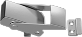
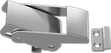
Tight-Hold Draw Latches
Style A | Style B | Style C |
 | ||
Style D | Style E | Style F |
 |  | |
Style G | Style H | Replacement Latch Strike Plates |
Latches | Replacement Latch Strike Plates | ||||||||||||||
|---|---|---|---|---|---|---|---|---|---|---|---|---|---|---|---|
Overall | Mounting | ||||||||||||||
Style | Material | Appearance | Latching Distance | Lg. | Wd. | Projection | Wt. Cap. | Fasteners Included | Screw Size | Each | Each | ||||
Screw On | |||||||||||||||
| A | 300 Series Stainless Steel | Polished | 3/8" | 1 7/16" | 1/2" | 5/16" | 200 lb. | No | No. 2 | 1794A51 | 00000 | 1734A31 | 00000 | ||
| B | Zinc-Plated Steel | Dull | 1 5/16" | 2 3/4" | 1 3/16" | 7/16" | 400 lb. | No | No. 6 | 1794A41 | 0000 | 1734A33 | 0000 | ||
| B | 300 Series Stainless Steel | Polished | 1 5/16" | 2 3/4" | 1 3/16" | 7/16" | 400 lb. | No | No. 6 | 1794A43 | 0000 | 1734A32 | 0000 | ||
| C | Zinc-Plated Steel | Dull | 1 5/16" | 2 3/4" | 1 1/8" | 1/2" | 400 lb. | No | No. 6 | 1734A34 | 0000 | 1734A33 | 0000 | ||
| C | 300 Series Stainless Steel | Polished | 1 5/16" | 2 3/4" | 1 1/8" | 1/2" | 400 lb. | No | No. 6 | 1734A37 | 00000 | 1734A32 | 0000 | ||
| D | Zinc-Plated Steel | Dull | 1 5/16" | 2 3/4" | 1 1/8" | 3/8" | 400 lb. | No | No. 6 | 1734A35 | 0000 | 1734A33 | 0000 | ||
| D | 300 Series Stainless Steel | Polished | 1 5/16" | 2 3/4" | 1 1/8" | 3/8" | 400 lb. | No | No. 6 | 1734A38 | 0000 | 1734A32 | 0000 | ||
| E | 300 Series Stainless Steel | Polished | 1 5/16" | 1 7/16" | 1/2" | 1/4" | 400 lb. | No | No. 5 | 1734A36 | 00000 | 1734A31 | 0000 | ||
| F | 304 Stainless Steel | Polished | 1 3/4" | 3 1/8" | 1 5/16" | 3/4" | Not Rated | No | No. 5 | 6343A77 | 00000 | ——— | 0 | ||
| G | Zinc-Plated Steel | Dull | 1 1/4" | 2 3/8" | 1 3/8" | 1/2" | Not Rated | No | No. 6 | 1734A12 | 0000 | ——— | 0 | ||
| G | Zinc-Plated Steel | Dull | 1 3/8" | 2 3/4" | 1 1/2" | 1/2" | Not Rated | No | No. 3 | 1734A45 | 0000 | ——— | 0 | ||
| G | Zinc-Plated Steel | Dull | 1 3/8" | 3 1/2" | 1 15/16" | 5/8" | Not Rated | No | No. 10, No. 12 | 1734A26 | 0000 | ——— | 0 | ||
| G | Zinc-Plated Steel | Dull | 1 7/16" | 3 7/8" | 1 7/8" | 5/8" | Not Rated | No | No. 5 | 1734A44 | 00000 | ——— | 0 | ||
| G | 300 Series Stainless Steel | Polished | 1 3/8" | 3 13/16" | 1 15/16" | 5/8" | Not Rated | No | No. 12, No. 5 | 1734A13 | 00000 | 1734A32 | 0000 | ||
| G | 304 Stainless Steel | Polished | 7/8" | 2" | 1 1/4" | 3/8" | Not Rated | No | No. 3 | 1734A46 | 0000 | ——— | 0 | ||
| G | 304 Stainless Steel | Polished | 1 3/8" | 2 11/16" | 1 1/2" | 9/16" | Not Rated | No | No. 5 | 1734A27 | 0000 | ——— | 0 | ||
| G | 304 Stainless Steel | Polished | 1 3/8" | 3 3/4" | 1 13/16" | 5/8" | Not Rated | No | No. 5 | 1734A47 | 00000 | ——— | 0 | ||
Weld On | |||||||||||||||
| C | Zinc-Plated Steel | Dull | 1 5/16" | 2 3/4" | 1 1/8" | 1/2" | 400 lb. | — | — | 1734A39 | 0000 | 1734A33 | 0000 | ||
| C | 300 Series Stainless Steel | Polished | 1 5/16" | 2 3/4" | 1 1/8" | 1/2" | 400 lb. | — | — | 1734A43 | 00000 | 1734A32 | 0000 | ||
| D | Zinc-Plated Steel | Dull | 1 5/16" | 2 3/4" | 1 1/8" | 3/8" | 400 lb. | — | — | 1734A41 | 0000 | 1734A33 | 0000 | ||
| D | 300 Series Stainless Steel | Polished | 1 5/16" | 2 3/4" | 1 1/8" | 3/8" | 400 lb. | — | — | 1734A42 | 0000 | 1734A32 | 0000 | ||
| H | Steel | Dull | 1 1/4" | 2 3/8" | 1 3/8" | 1/2" | Not Rated | — | — | 1734A14 | 0000 | ——— | 0 | ||
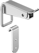
Turn-to-Open Keyed Draw Locks
 | 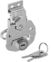 |
Lift and turn the handle 180° to open and close this lock. It has a spring-loaded handle that provides a tight hold and compensates for slight misalignment. It's keyed alike, choose it if you need several locks that open with the same key. Capacity is the maximum amount of force the latch can withstand.
Overall | Mounting | ||||||||||||||
|---|---|---|---|---|---|---|---|---|---|---|---|---|---|---|---|
Material | Appearance | Latching Distance | Lg. | Wd. | Projection | Wt. Cap., lb. | Fasteners Included | Screw Size | Key No. | No. of Keys Included | Features | Each | |||
| Zinc-Plated Steel | Dull | 3/4" | 3 1/2" | 2 1/2" | 13/16" | 400 | No | No. 8 | 801 | 2 | Spring-Loaded Handle | 1406A57 | 000000 | ||
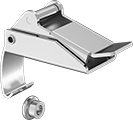
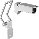
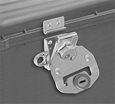
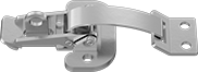
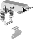
Corner-Mount Tight-Hold Padlockable Draw Latches with Safety Catch
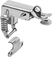 |
Mount this latch on a corner to draw perpendicular surfaces together. It has a safety catch to prevent accidental opening. Designed with compression springs to withstand vibration better than standard padlockable draw latches, it offers a more secure hold. The overall length listed includes the strike plate.
Overall | Mounting | Straight Strike Plate | ||||||||||||
|---|---|---|---|---|---|---|---|---|---|---|---|---|---|---|
Material | Appearance | Latching Distance | Lg. | Wd. | Projection | Wt. Cap. | For Max. Padlock Shackle Dia. | Fasteners Included | Screw Size | Features | Each | |||
| 304 Stainless Steel | Polished | 1 1/8" | 2 9/16" | 1 9/16" | 5/8" | Not Rated | 3/16" | No | M4 | Safety Catch | 6148A25 | 000000 | ||
Padlockable Draw Latches
 |  |  |  |
Style B | Style G | Style H | Style J |
Latches | Replacement Latch Strike Plates | ||||||||||||||||
|---|---|---|---|---|---|---|---|---|---|---|---|---|---|---|---|---|---|
Overall | Mounting | ||||||||||||||||
Style | Material | Appearance | Latching Distance | Lg. | Wd. | Projection | Wt. Cap. | For Max. Padlock Shackle Dia. | Fasteners Included | Screw Size | Pkg. Qty. | Pkg. | Each | ||||
Screw On | |||||||||||||||||
| B | Zinc-Plated Steel | Polished | 2 9/16" | 2 1/2" | 7/8" | 3/4" | Not Rated | 1/4" | No | No. 6 | 1 | 1734A51 | 00000 | 1734A61 | 00000 | ||
| B | 300 Series Stainless Steel | Dull | 2 9/16" | 2 1/2" | 7/8" | 3/4" | Not Rated | 1/4" | No | No. 6 | 1 | 1734A52 | 00000 | 1734A62 | 0000 | ||
| G | 300 Series Stainless Steel | Dull | 1 5/16" | 2 3/4" | 1 3/16" | 15/16" | 400 lb. | 3/8" | No | No. 6 | 1 | 1794A54 | 00000 | ——— | 0 | ||
| H | Zinc-Plated Steel | Polished | 3 7/8" | 3 7/8" | 1 1/4" | 15/16" | Not Rated | 3/8" | No | No. 10 | 1 | 1734A53 | 0000 | 1734A63 | 0000 | ||
| H | 300 Series Stainless Steel | Dull | 3 7/8" | 3 7/8" | 1 1/4" | 15/16" | Not Rated | 3/8" | No | No. 10 | 1 | 1734A54 | 00000 | 1734A64 | 0000 | ||
| J | Zinc-Plated Steel | Polished | 4 1/2" | 3 5/8" | 1 7/8" | 7/8" | Not Rated | 1/4" | No | No. 10 | 1 | 1734A59 | 00000 | 1734A67 | 0000 | ||
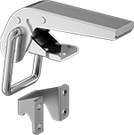
Keyed Corner-Mount Draw Locks
 |
Secure cases, toolboxes, and other containers—these locks reach around outside corners to draw two surfaces together. They’re keyed alike, so choose them if you need several locks that open with the same key. The overall length listed includes the strike plate.
Overall | Mounting | Straight Strike Plate | ||||||||||||
|---|---|---|---|---|---|---|---|---|---|---|---|---|---|---|
Material | Appearance | Latching Distance | Lg. | Wd. | Projection | Wt. Cap. | Fasteners Included | Screw Size | Key No. | No. of Keys Included | Each | |||
| 304 Stainless Steel | Polished | 3/4" | 2 1/16" | 1" | 7/16" | Not Rated | No | No. 5 | 0200 | 2 | 4047N13 | 000000 | ||
| 304 Stainless Steel | Polished | 1" | 2 9/16" | 1 1/4" | 1/2" | Not Rated | No | No. 8 | 0200 | 2 | 4047N12 | 00000 | ||
| 304 Stainless Steel | Polished | 1 1/4" | 3 1/4" | 1 9/16" | 5/8" | Not Rated | No | No. 8 | 0200 | 2 | 4047N11 | 00000 | ||
Tight-Hold Padlockable Draw Latches
 |  | |
Style A | Style B | Replacement Latch Strike Plates |
Latches | Replacement Latch Strike Plates | |||||||||||||||
|---|---|---|---|---|---|---|---|---|---|---|---|---|---|---|---|---|
Overall | Mounting | |||||||||||||||
Style | Material | Appearance | Latching Distance | Lg. | Wd. | Projection | Wt. Cap. | For Max. Padlock Shackle Dia. | Fasteners Included | Screw Size | Each | Each | ||||
| A | Zinc-Plated Steel | Polished | 1 1/16" | 3" | 1 3/8" | 13/16" | Not Rated | 5/16" | No | No. 6 | 1734A11 | 00000 | 1734A71 | 00000 | ||
| A | Zinc-Plated Steel | Polished | 1 1/4" | 3 5/8" | 1 13/16" | 15/16" | Not Rated | 3/8" | No | No. 10, No. 12 | 1734A15 | 00000 | 1734A72 | 0000 | ||
| B | Zinc-Plated Steel | Polished | 4 1/16" | 3 3/16" | 1 7/8" | 7/8" | Not Rated | 3/8" | No | No. 10 | 1734A55 | 0000 | 1734A65 | 0000 | ||
| B | 300 Series Stainless Steel | Dull | 4 1/16" | 3 3/16" | 1 7/8" | 7/8" | Not Rated | 3/8" | No | No. 10 | 1734A56 | 00000 | 1734A66 | 0000 | ||
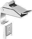
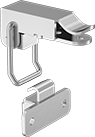
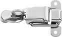
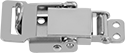
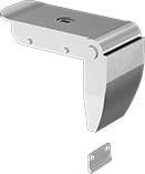
Corner-Mount Tight-Hold Draw Latches
 | 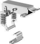 |
Straight Strike Plate with Safety Catch | 90° Angle Strike Plate with Safety Catch |
Mount these latches on a corner to draw perpendicular surfaces together. Designed with compression springs to withstand vibration better than standard draw latches, they offer a more secure hold. The overall length listed includes the strike plate.
Safety Catch—Latches with a safety catch prevent accidental opening.
Overall | Mounting | Straight Strike Plate | 90° Angle Strike Plate | |||||||||||
|---|---|---|---|---|---|---|---|---|---|---|---|---|---|---|
Material | Appearance | Latching Distance | Lg. | Wd. | Projection | Wt. Cap. | Fasteners Included | Screw Size | Each | Each | ||||
Draw Latches | ||||||||||||||
| 304 Stainless Steel | Polished | 1 1/8" | 2 1/4" | 1 9/16" | 5/8" | Not Rated | No | M4 | 6148A16 | 000000 | 6148A15 | 000000 | ||
Safety Catch | ||||||||||||||
| 304 Stainless Steel | Polished | 2 3/16" | 2 3/8" | 1 11/16" | 5/8" | Not Rated | No | M3 | 6148A37 | 00000 | ——— | 0 | ||
| 304 Stainless Steel | Polished | 2 9/16" | 3 5/8" | 2 1/4" | 3/4" | Not Rated | No | M4 | 6148A36 | 00000 | 6148A35 | 00000 | ||
| 304 Stainless Steel | Polished | 2 13/16" | 4 3/8" | 2 1/2" | 1" | Not Rated | No | M5 | 6148A34 | 00000 | 6148A33 | 00000 | ||
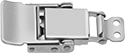
Tight-Hold Turn-to-Open Draw Latches
 |
Surface Mount |
With a spring-loaded handle, these hold tighter than other turn-to-open draw latches and compensate for slight misalignment. Lift and turn the handle 180° to open and close these latches. Capacity is the maximum amount of force the latch can withstand.
Overall | Mounting | |||||||||||
|---|---|---|---|---|---|---|---|---|---|---|---|---|
Material | Appearance | Latching Distance | Lg. | Wd. | Projection | Wt. Cap., lb. | Fasteners Included | Screw Size | Each | |||
Surface Mount | ||||||||||||
| Zinc-Plated Steel | Dull | 3/4" | 2 3/8" | 1 15/16" | 5/8" | 300 | No | No. 4 | 1406A48 | 00000 | ||
| Zinc-Plated Steel | Dull | 3/4" | 2 3/4" | 2 1/2" | 13/16" | 400 | No | No. 8 | 1406A45 | 00000 | ||
| Zinc-Plated Steel | Dull | 1 7/8" | 4 15/16" | 3 1/4" | 13/16" | 500 | No | No. 10 | 1406A73 | 00000 | ||
| Black Powder-Coated Steel | Dull | 1 1/4" | 2 5/8" | 2 1/16" | 3/4" | 270 | No | No. 8 | 1406A31 | 00000 | ||
| 300 Series Stainless Steel | Dull | 3/4" | 2 3/8" | 1 15/16" | 5/8" | 300 | No | No. 4 | 1406A51 | 00000 | ||
| 300 Series Stainless Steel | Dull | 1 1/4" | 2 7/8" | 2 1/16" | 3/4" | 190 | No | No. 8 | 1406A61 | 00000 | ||
| 300 Series Stainless Steel | Dull | 1 7/8" | 4 15/16" | 3 1/4" | 13/16" | 500 | No | No. 10 | 1406A74 | 00000 | ||
