



























Filter by


Maximum Holding Torque
Shaft Diameter
Maximum Rotation Speed


Component
Mounting Position
Thrust Load Capacity
Direction of Operation


Wire Connection
Face Shape

Export Control Classification Number (ECCN)

DFARS Specialty Metals
Stepper Motors
Motors
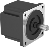 | 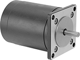 |
Square Body | Round Body |
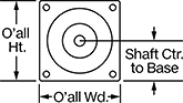 | 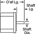 |
These stepper motors are good for precise, repetitive movements, such as those made by the head of a 3D printer. Similar to the hands of a clock, their shaft turns in small, equal increments. When the shaft stops, it holds its position even when a counteracting force is applied to the load. You can control the position of the load without having to configure encoders or sensors. All are bipolar hybrid stepper motors, so the current can flow in both directions. This helps them deliver higher torque, precision, and efficiency than unipolar stepper motors.
All motors require a controller and drive (not included).
For the Manufacturer User Manual, click on a part number and select Product Detail.
8 Wire Leads—Motors with 8 wire leads can be connected to a drive in two different ways, so you can choose between more speed or more torque. Depending on your application, you could configure the motor for high torque at low speeds or for low torque at high speeds.
2 Shafts—When relative positioning is critical, such as coordinating motion in a multi-axis system, choose a motor with two shafts and mount an encoder (not included) on one of them. The encoder monitors the position of the shaft and reports back to the controller.
Maximum Holding Torque—Holding torque is the force needed to move the shaft out of position when it is stationary. When the shaft is in motion, torque generally decreases as speed increases. Use a torque-speed curve to confirm which motor will work for your application. Click on a part number and select “Product Detail” to view the curve for a motor.
Full Step Increment—Full step increment is the rotation of the shaft from one position to the next. A smaller full step increment means the rotor has more teeth, producing smoother and more precise motion. 1.8° is considered standard.
Overall | Shaft | Temp. Range, ° F | |||||||||||||||||
|---|---|---|---|---|---|---|---|---|---|---|---|---|---|---|---|---|---|---|---|
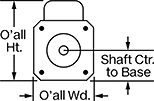
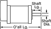
Max. Holding Torque, in·ozf | Max. Rotation Speed, rpm | Max. Current per Phase, amp | Full Step Increment | Stepper Motor Polarity | No. of Wire Leads | Lg. | Wd. | Ht. | Dia. | Lg. | Ctr.-to-Base Lg. | Type | No. of Shafts | Min. | Max. | Each | |||
Square Body | |||||||||||||||||||
NEMA 23 Frame Size | |||||||||||||||||||
| 73 | 1,800 | 2.8 | 1.8° | Bipolar | 8 | 2.6" | 2.3" | 2.3" | 1/4" | 3/4" | 1.13" | D-Profile | 1 | 0 | 120 | 6627T261 | 0000000 | ||
| 76 | 3,000 | 4.2 | 1.8° | Bipolar | 8 | 2.4" | 2.3" | 2.3" | 1/4" | 13/16" | 1.11" | D-Profile | 1 | 0 | 120 | 6627T611 | 00000 | ||
| 173.5 | 1,000 | 2.8 | 1.8° | Bipolar | 4 | 3" | 2.3" | 2.3" | 1/4" | 3/4" | 1.13" | D-Profile | 1 | 0 | 120 | 6627T53 | 000000 | ||
| 173.9 | 1,000 | 2.8 | 1.8° | Bipolar | 4 | 3.6" | 2.3" | 2.3" | 1/4" | 3/4" | 1.13" | D-Profile | 2 | 0 | 120 | 6627T922 | 000000 | ||
| 178 | 2,700 | 5.6 | 1.8° | Bipolar | 8 | 3" | 2.3" | 2.3" | 1/4" | 13/16" | 1.11" | D-Profile | 1 | 0 | 120 | 6627T621 | 00000 | ||
| 198.2 | 400 | 1.5 | 0.9° | Bipolar | 4 | 3" | 2.3" | 2.3" | 1/4" | 3/4" | 1.13" | D-Profile | 1 | 0 | 120 | 6627T242 | 000000 | ||
| 205 | 750 | 2.8 | 1.8° | Bipolar | 8 | 3.9" | 2.3" | 2.3" | 1/4" | 3/4" | 1.13" | D-Profile | 1 | 0 | 120 | 6627T271 | 000000 | ||
| 237 | 1,175 | 4 | 1.8° | Bipolar | 4 | 3.9" | 2.3" | 2.3" | 1/4" | 3/4" | 1.13" | D-Profile | 1 | 0 | 120 | 6627T54 | 000000 | ||
| 262 | 3,000 | 7 | 1.8° | Bipolar | 8 | 3.8" | 2.3" | 2.3" | 1/4" | 13/16" | 1.11" | D-Profile | 1 | 0 | 120 | 6627T631 | 000000 | ||
| 339.8 | 250 | 1.5 | 0.9° | Bipolar | 4 | 3.9" | 2.3" | 2.3" | 1/4" | 3/4" | 1.13" | D-Profile | 1 | 0 | 120 | 6627T251 | 000000 | ||
| 425 | 2,100 | 7.06 | 1.8° | Bipolar | 8 | 5.3" | 2.3" | 2.3" | 1/4" | 13/16" | 1.11" | D-Profile | 1 | 0 | 120 | 6627T641 | 000000 | ||
| 467.3 | 300 | 2 | 1.8° | Bipolar | 4 | 3.8" | 2.3" | 2.3" | 1/4" | 3/4" | 1.13" | D-Profile | 1 | 0 | 120 | 6627T923 | 000000 | ||
| 600.4 | 1,300 | 6.5 | 1.8° | Bipolar | 4 | 4.2" | 2.3" | 2.3" | 1/4" | 3/4" | 1.13" | D-Profile | 1 | 0 | 120 | 6627T161 | 000000 | ||
NEMA 24 Frame Size | |||||||||||||||||||
| 153 | 2,100 | 2.8 | 1.8° | Bipolar | 8 | 2.7" | 2.4" | 2.4" | 1/4" | 13/16" | 1.18" | D-Profile | 1 | 0 | 120 | 6627T551 | 00000 | ||
| 229 | 2,100 | 2.8 | 1.8° | Bipolar | 8 | 3" | 2.4" | 2.4" | 1/4" | 13/16" | 1.18" | D-Profile | 1 | 0 | 120 | 6627T561 | 00000 | ||
| 292 | 3,000 | 5.6 | 1.8° | Bipolar | 8 | 3.5" | 2.4" | 2.4" | 1/4" | 13/16" | 1.18" | D-Profile | 1 | 0 | 120 | 6627T571 | 000000 | ||
| 380 | 2,400 | 2.8 | 1.8° | Bipolar | 8 | 3.8" | 2.4" | 2.4" | 1/4" | 13/16" | 1.18" | D-Profile | 1 | 0 | 120 | 6627T581 | 000000 | ||
| 431 | 1,800 | 5.6 | 1.8° | Bipolar | 8 | 4.3" | 2.4" | 2.4" | 1/4" | 13/16" | 1.18" | D-Profile | 1 | 0 | 120 | 6627T591 | 000000 | ||
Round Body | |||||||||||||||||||
NEMA 23 Frame Size | |||||||||||||||||||
| 76.4 | 1,600 | 0.35 | 1.8° | Bipolar | 4 | 2.4" | 2.3" | 2.3" | 1/4" | 3/4" | 1.13" | Solid | 1 | 0 | 120 | 6627T321 | 000000 | ||
| 106.2 | 975 | 1.4 | 1.8° | Bipolar | 4 | 2.8" | 2.3" | 2.3" | 1/4" | 3/4" | 1.13" | Solid | 1 | 0 | 120 | 6627T331 | 000000 | ||
| 131.7 | 1,900 | 3.1 | 1.8° | Bipolar | 4 | 3.1" | 2.3" | 2.3" | 1/4" | 3/4" | 1.13" | Solid | 1 | 0 | 120 | 6627T341 | 000000 | ||
| 175.6 | 1,100 | 4 | 1.8° | Bipolar | 4 | 3.8" | 2.3" | 2.3" | 1/4" | 3/4" | 1.13" | Solid | 1 | 0 | 120 | 6627T351 | 000000 | ||
Motor/Drives
 |
 |
 |
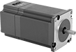
Reduce the size and complexity of your stepper motor setup—these motors have a drive built in, so you don’t need to run cable to a standalone drive. The drive delivers power to the motor based on signals from a PLC, pulse generator, or other controller. These motors are good for precise, repetitive movements, such as those made by the head of a 3D printer. Similar to the hands of a clock, their shaft turns in small, equal increments for smooth motion. When the shaft stops, it holds its position even when a counteracting force is applied to the load. You can control the position of the load without having to configure encoders or sensors. All are bipolar hybrid stepper motors, so the current can flow in both directions. This helps them deliver higher torque, precision, and efficiency than unipolar stepper motors.
For the Manufacturer User Manual, click on a part number and select Product Detail.
Maximum Holding Torque—Holding torque is the force needed to move the shaft out of position when it is stationary. When the shaft is in motion, torque generally decreases as speed increases. Use a torque-speed curve to confirm which motor will work for your application. Click on a part number and select “Product Detail” to view the curve for a motor.
Full Step Increment—Full step increment is the rotation of the shaft from one position to the next. A smaller full step increment means the rotor has more teeth, producing smoother and more precise motion. 1.8° is considered standard.
Step Resolution—You can adjust the step resolution down to 1/256 of a full step, which translates to 51,200 microsteps per revolution. Increasing the number of steps directs an even more precise position and reduces the step-step-step motion to mimic a smooth, continuous rotation. The higher the number of step resolution settings, the greater the flexibility you have for determining the size of the motor’s step.
Current per Phase, amp | Overall | Shaft | Temp. Range, ° F | ||||||||||||||||||
|---|---|---|---|---|---|---|---|---|---|---|---|---|---|---|---|---|---|---|---|---|---|
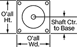
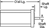
Max. Holding Torque, in·ozf | Max. Rotation Speed, rpm | Min. | Max. | Voltage, V DC | Full Step Increment | Step Resolution | Stepper Motor Polarity | No. of Wire Leads | Lg. | Wd. | Ht. | Dia. | Lg. | Ctr.-to-Base Lg. | Type | Min. | Max. | Each | |||
Square Body | |||||||||||||||||||||
NEMA 23 Frame Size | |||||||||||||||||||||
| 76 | 1,500 | 0.21 | 2.1 | 12 to 24 | 1.8° | 1, 1/2, 1/8, 1/64, 1/256 | Bipolar | 7 | 3.8" | 2.2" | 2.2" | 1/4" | 3/4" | 1.11" | D-Profile | 0 | 120 | 6627T113 | 0000000 | ||
| 175 | 1,500 | 0.21 | 2.1 | 12 to 24 | 1.8° | 1, 1/2, 1/8, 1/64, 1/256 | Bipolar | 7 | 4.2" | 2.2" | 2.2" | 1/4" | 3/4" | 1.11" | D-Profile | 0 | 120 | 6627T114 | 000000 | ||
| 262 | 1,500 | 0.21 | 2.1 | 12 to 24 | 1.8° | 1, 1/2, 1/8, 1/64, 1/256 | Bipolar | 7 | 5.1" | 2.2" | 2.2" | 1/4" | 3/4" | 1.11" | D-Profile | 0 | 120 | 6627T115 | 000000 | ||
| 425 | 1,500 | 0.21 | 2.1 | 12 to 24 | 1.8° | 1, 1/2, 1/8, 1/64, 1/256 | Bipolar | 7 | 6.6" | 2.2" | 2.2" | 1/4" | 3/4" | 1.11" | D-Profile | 0 | 120 | 6627T116 | 000000 | ||
Motor/Encoders
 |
 |
 |
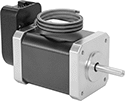
To improve positioning accuracy, these stepper motors have a built-in encoder that monitors the real-time speed and position of the shaft. It sends that data to a controller (not included), which adjusts or stops the shaft if it isn’t in the right place. This makes them useful when relative positioning is critical, such as when coordinating motion between two motors. Stepper motors are good for precise, repetitive movements. Similar to the hands of a clock, their shaft turns in small, equal increments for smooth motion. When the shaft stops, it holds its position even when a counteracting force is applied to the load. All are bipolar hybrid stepper motors, so the current can flow in both directions. This helps them deliver higher torque, precision, and efficiency than unipolar stepper motors.
All motors require a controller and drive (not included).
For the Manufacturer User Manual, click on a part number and select Product Detail.
2 Shafts—When relative positioning is critical, such as coordinating motion in a multi-axis system, choose a motor with two shafts and mount an encoder (not included) on one of them. The encoder monitors the position of the shaft and reports back to the controller.
Maximum Holding Torque—Holding torque is the force needed to move the shaft out of position when it is stationary. When the shaft is in motion, torque generally decreases as speed increases. Use a torque-speed curve to confirm which motor will work for your application. Click on a part number and select “Product Detail” to view the curve for a motor.
Full Step Increment—Full step increment is the rotation of the shaft from one position to the next. A smaller full step increment means the rotor has more teeth, producing smoother and more precise motion. 1.8° is considered standard.
Overall | Shaft | Temp. Range, ° F | ||||||||||||||||||||
|---|---|---|---|---|---|---|---|---|---|---|---|---|---|---|---|---|---|---|---|---|---|---|
Max. Holding Torque, in·ozf | Max. Rotation Speed, rpm | Max. Current per Phase, amp | Voltage, V DC | Full Step Increment | Stepper Motor Polarity | Encoder Positioning Type | No. of Counts per Rev. | No. of Wire Leads | Lg. | Wd. | Ht. | Dia. | Lg. | Ctr.-to-Base Lg. | Type | No. of Shafts | Min. | Max. | Each | |||
Square Body | ||||||||||||||||||||||
NEMA 23 Frame Size | ||||||||||||||||||||||
| 181 | 600 | 2.8 | 5 | 1.8° | Bipolar | Incremental | 1,000 | 4 | 3.7" | 2.6" | 2.3" | 1/4" | 3/4" | 1.13" | D-Profile | 2 | 0 | 120 | 6627T441 | 0000000 | ||
| 237 | 525 | 4 | 5 | 1.8° | Bipolar | Incremental | 1,000 | 4 | 4.6" | 2.6" | 2.3" | 1/4" | 3/4" | 1.13" | D-Profile | 2 | 0 | 120 | 6627T451 | 000000 | ||
| 355 | 900 | 6 | 5 | 1.8° | Bipolar | Incremental | 1,000 | 4 | 4.9" | 2.6" | 2.3" | 1/4" | 3/4" | 1.13" | D-Profile | 2 | 0 | 120 | 6627T461 | 000000 | ||
| 467.3 | 300 | 2 | 5 | 1.8° | Bipolar | Incremental | 1,000 | 4 | 4.5" | 2.5" | 2.3" | 1/4" | 3/4" | 1.11" | D-Profile | 2 | 0 | 120 | 6627T471 | 000000 | ||
| 600.4 | 1,300 | 6.5 | 5 | 1.8° | Bipolar | Incremental | 1,000 | 4 | 4.9" | 2.6" | 2.3" | 1/4" | 3/4" | 1.13" | D-Profile | 2 | 0 | 120 | 6627T481 | 000000 | ||
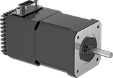
Stepper Motors with Integrated Motion Control
 |
Current per Phase, amp | Overall | Shaft | Temp. Range, ° F | |||||||||||||||||
|---|---|---|---|---|---|---|---|---|---|---|---|---|---|---|---|---|---|---|---|---|
Max. Holding Torque, in·ozf | Max. Rotation Speed, rpm | Min. | Max. | Voltage, V DC | Full Step Increment | Step Resolution | No. of Inputs/Outputs | Lg. | Wd. | Ht. | Dia. | Lg. | Ctr.-to-Base Lg. | Type | Min. | Max. | Each | |||
Motor/Controller/Drives | ||||||||||||||||||||
NEMA 23 Frame Size | ||||||||||||||||||||
| 76 | 1,500 | 0.21 | 2.1 | 12 to 24 | 1.8° | 1, 1/2, 1/4, 1/8 | 2 Digital-Inputs, 1 Digital-Output | 3.7" | 2.3" | 2.3" | 1/4" | 13/16" | 1.17" | D-Profile | 0 | 120 | 6627T122 | 0000000 | ||
| 175 | 1,500 | 0.21 | 2.1 | 12 to 24 | 1.8° | 1, 1/2, 1/4, 1/8 | 2 Digital-Inputs, 1 Digital-Output | 4.3" | 2.3" | 2.3" | 1/4" | 13/16" | 1.17" | D-Profile | 0 | 120 | 6627T123 | 000000 | ||
| 262 | 1,500 | 0.21 | 2.1 | 12 to 24 | 1.8° | 1, 1/2, 1/4, 1/8 | 2 Digital-Inputs, 1 Digital-Output | 5.1" | 2.3" | 2.3" | 1/4" | 13/16" | 1.17" | D-Profile | 0 | 120 | 6627T124 | 000000 | ||
| 425 | 1,500 | 0.21 | 2.1 | 12 to 24 | 1.8° | 1, 1/2, 1/4, 1/8 | 2 Digital-Inputs, 1 Digital-Output | 6.6" | 2.3" | 2.3" | 1/4" | 13/16" | 1.17" | D-Profile | 0 | 120 | 6627T125 | 000000 | ||
Motor/Controller/Drive/Encoders | ||||||||||||||||||||
NEMA 23 Frame Size | ||||||||||||||||||||
| 100.5 | 2,475 | 0.3 | 3 | 12 to 40 | 1.8° | 1, 1/2, 1/4, 1/8, 1/16, 1/32, 1/64, 1/128, 1/256 | 4 Digital-Inputs/Outputs | 3.8" | 2.3" | 2.3" | 1/4" | 3/4" | 1.13" | D-Profile | 0 | 120 | 6627T101 | 000000 | ||
| 182.5 | 2,000 | 0.3 | 3 | 12 to 40 | 1.8° | 1, 1/2, 1/4, 1/8, 1/16, 1/32, 1/64, 1/128, 1/256 | 4 Digital-Inputs/Outputs | 4.3" | 2.3" | 2.3" | 1/4" | 3/4" | 1.13" | D-Profile | 0 | 120 | 6627T102 | 000000 | ||
| 294.5 | 820 | 0.3 | 3 | 12 to 40 | 1.8° | 1, 1/2, 1/4, 1/8, 1/16, 1/32, 1/64, 1/128, 1/256 | 4 Digital-Inputs/Outputs | 5.1" | 2.3" | 2.3" | 1/4" | 3/4" | 1.13" | D-Profile | 0 | 120 | 6627T103 | 000000 | ||
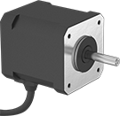
Wet-Environment Stepper Motors
Motors
 |
Maximum Holding Torque—Holding torque is the force needed to move the shaft out of position when it is stationary. When the shaft is in motion, torque generally decreases as speed increases. Use a torque-speed curve to confirm which motor will work for your application. Click on a part number and select “Product Detail” to view the curve for a motor.
Full Step Increment—Full step increment is the rotation of the shaft from one position to the next. A smaller full step increment means the rotor has more teeth, producing smoother and more precise motion. 1.8° is considered standard.
Overall | Shaft | Temp. Range, ° F | ||||||||||||||||||
|---|---|---|---|---|---|---|---|---|---|---|---|---|---|---|---|---|---|---|---|---|
Max. Holding Torque, in·ozf | Max. Rotation Speed, rpm | Max. Current per Phase, amp | Full Step Increment | Stepper Motor Polarity | No. of Wire Leads | Lg. | Wd. | Ht. | Dia. | Lg. | Ctr.-to-Base Lg. | Type | No. of Shafts | Min. | Max. | Enclosure Rating | Each | |||
Square Body | ||||||||||||||||||||
NEMA 23 Frame Size | ||||||||||||||||||||
| 173.5 | 1,000 | 2.8 | 1.8° | Bipolar | 4 | 3.1" | 2.3" | 2.3" | 1/4" | 3/4" | 1.13" | D-Profile | 1 | 0 | 120 | IP65 | 5958N102 | 0000000 | ||
| 237 | 1,175 | 4 | 1.8° | Bipolar | 4 | 4" | 2.3" | 2.3" | 1/4" | 3/4" | 1.13" | D-Profile | 1 | 0 | 120 | IP65 | 5958N103 | 000000 | ||
| 274 | 820 | 2.8 | 1.8° | Bipolar | 4 | 4" | 2.3" | 2.3" | 1/4" | 3/4" | 1.13" | D-Profile | 1 | 0 | 120 | IP65 | 5958N12 | 000000 | ||
| 352.5 | 3,000 | 6 | 1.8° | Bipolar | 4 | 4.4" | 2.3" | 2.3" | 1/4" | 3/4" | 1.13" | D-Profile | 1 | 0 | 120 | IP65 | 5958N104 | 000000 | ||
High-Temperature Stepper Motors
Motors
 |
Maximum Holding Torque—Holding torque is the force needed to move the shaft out of position when it is stationary. When the shaft is in motion, torque generally decreases as speed increases. Use a torque-speed curve to confirm which motor will work for your application. Click on a part number and select “Product Detail” to view the curve for a motor.
Full Step Increment—Full step increment is the rotation of the shaft from one position to the next. A smaller full step increment means the rotor has more teeth, producing smoother and more precise motion. 1.8° is considered standard.
Overall | Shaft | Temp. Range, ° F | |||||||||||||||||
|---|---|---|---|---|---|---|---|---|---|---|---|---|---|---|---|---|---|---|---|
Max. Holding Torque, in·ozf | Max. Rotation Speed, rpm | Max. Current per Phase, amp | Full Step Increment | Stepper Motor Polarity | No. of Wire Leads | Lg. | Wd. | Ht. | Dia. | Lg. | Ctr.-to-Base Lg. | Type | No. of Shafts | Min. | Max. | Each | |||
Square Body | |||||||||||||||||||
NEMA 23 Frame Size | |||||||||||||||||||
| 181 | 1,000 | 2.8 | 1.8° | Bipolar | 4 | 3" | 2.3" | 2.3" | 1/4" | 3/4" | 1.13" | D-Profile | 1 | -40 | 212 | 8643N14 | 0000000 | ||
| 237 | 1,175 | 4 | 1.8° | Bipolar | 4 | 3.9" | 2.3" | 2.3" | 1/4" | 3/4" | 1.13" | D-Profile | 1 | -40 | 212 | 8643N15 | 000000 | ||
Precision Beam Couplings
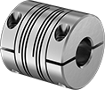 |
Spiral Cut |
Misalignment Capability | |||||||||||||
|---|---|---|---|---|---|---|---|---|---|---|---|---|---|
Choose a Shaft Dia. | OD | Overall Lg. | Max. Rotation Speed, rpm | Max. Torque, in·lbf | Parallel | Angular | Axial | For Shaft Type | Shaft Mount Type | Each | |||
Spiral Cut | |||||||||||||
303 Stainless Steel | |||||||||||||
| 3/16" × 1/4" | 5/8" | 1" | 6,000 | 18 | 0.008" | 3° | 0.005" | Round | Clamp On | 6259K12 | 0000000 | ||
| 1/4" × 3/16" | 3/4" | 1 1/4" | 6,000 | 31 | 0.008" | 3° | 0.005" | Round | Clamp On | 6259K62 | 000000 | ||
| 1/4" × 1/4" | 5/8" | 1" | 6,000 | 18 | 0.008" | 3° | 0.005" | Round | Clamp On | 6259K13 | 000000 | ||
| 1/4" × 1/4" | 3/4" | 1 1/4" | 6,000 | 31 | 0.008" | 3° | 0.005" | Round | Clamp On | 6259K63 | 000000 | ||
| 1/4" × 1/4" | 1" | 1 1/2" | 6,000 | 50 | 0.015" | 3° | 0.01" | Round | Clamp On | 6259K24 | 000000 | ||
| 1/4" × 5/16" | 3/4" | 1 1/4" | 6,000 | 31 | 0.008" | 3° | 0.005" | Round | Clamp On | 6259K65 | 000000 | ||
| 1/4" × 5/16" | 1" | 1 1/2" | 6,000 | 50 | 0.015" | 3° | 0.01" | Round | Clamp On | 6259K17 | 000000 | ||
| 3/8" × 1/4" | 1" | 1 1/2" | 6,000 | 50 | 0.015" | 3° | 0.01" | Round | Clamp On | 6259K26 | 000000 | ||
Aluminum | |||||||||||||
| 5/32" × 1/4" | 5/8" | 7/8" | 10,000 | 12 | 0.01" | 3° | 0.008" | Round | Clamp On | 6208K387 | 00000 | ||
| 3/16" × 1/4" | 5/8" | 7/8" | 10,000 | 12 | 0.01" | 3° | 0.008" | Round | Clamp On | 6208K388 | 00000 | ||
| 3/16" × 1/4" | 3/4" | 3/4" | 10,000 | 20 | 0.006" | 3° | 0.006" | Round | Clamp On | 6208K432 | 000000 | ||
| 1/4" × 1/16" | 3/4" | 3/4" | 10,000 | 20 | 0.006" | 3° | 0.006" | Round | Set Screw | 9861T426 | 00000 | ||
| 1/4" × 3/32" | 3/4" | 3/4" | 10,000 | 20 | 0.006" | 3° | 0.006" | Round | Clamp On | 6208K427 | 000000 | ||
| 1/4" × 3/32" | 3/4" | 3/4" | 10,000 | 20 | 0.006" | 3° | 0.006" | Round | Set Screw | 9861T427 | 00000 | ||
| 1/4" × 1/8" | 5/8" | 7/8" | 10,000 | 12 | 0.01" | 3° | 0.008" | Round | Clamp On | 6208K386 | 00000 | ||
| 1/4" × 1/8" | 5/8" | 7/8" | 10,000 | 12 | 0.01" | 3° | 0.008" | Round | Set Screw | 9861T317 | 00000 | ||
| 1/4" × 1/8" | 3/4" | 3/4" | 10,000 | 20 | 0.006" | 3° | 0.006" | Round | Clamp On | 6208K428 | 000000 | ||
| 1/4" × 1/8" | 3/4" | 3/4" | 10,000 | 20 | 0.006" | 3° | 0.006" | Round | Set Screw | 9861T428 | 00000 | ||
| 1/4" × 1/8" | 3/4" | 1" | 10,000 | 25 | 0.01" | 3° | 0.008" | Round | Clamp On | 6208K454 | 00000 | ||
| 1/4" × 1/8" | 3/4" | 1" | 10,000 | 25 | 0.01" | 3° | 0.008" | Round | Set Screw | 9861T525 | 00000 | ||
| 1/4" × 1/8" | 1" | 1 1/2" | 10,000 | 63 | 0.015" | 5° | 0.01" | Round | Clamp On | 6208K521 | 00000 | ||
| 1/4" × 5/32" | 5/8" | 7/8" | 10,000 | 12 | 0.01" | 3° | 0.008" | Round | Set Screw | 9861T319 | 00000 | ||
| 1/4" × 5/32" | 3/4" | 3/4" | 10,000 | 20 | 0.006" | 3° | 0.006" | Round | Clamp On | 6208K431 | 000000 | ||
| 1/4" × 5/32" | 3/4" | 3/4" | 10,000 | 20 | 0.006" | 3° | 0.006" | Round | Set Screw | 9861T429 | 00000 | ||
| 1/4" × 5/32" | 3/4" | 1" | 10,000 | 25 | 0.01" | 3° | 0.008" | Round | Clamp On | 6208K455 | 00000 | ||
| 1/4" × 5/32" | 3/4" | 1" | 10,000 | 25 | 0.01" | 3° | 0.008" | Round | Set Screw | 9861T527 | 00000 | ||
| 1/4" × 5/32" | 1" | 1 1/2" | 10,000 | 63 | 0.01" | 3° | 0.008" | Round | Set Screw | 9861T721 | 00000 | ||
| 1/4" × 5/32" | 1" | 1 1/2" | 10,000 | 63 | 0.015" | 5° | 0.01" | Round | Clamp On | 6208K522 | 00000 | ||
| 1/4" × 3/16" | 5/8" | 7/8" | 10,000 | 12 | 0.01" | 3° | 0.008" | Round | Set Screw | 9861T316 | 00000 | ||
| 1/4" × 3/16" | 3/4" | 3/4" | 10,000 | 20 | 0.006" | 3° | 0.006" | Round | Set Screw | 9861T432 | 00000 | ||
| 1/4" × 3/16" | 3/4" | 1" | 10,000 | 25 | 0.01" | 3° | 0.008" | Round | Clamp On | 6208K456 | 00000 | ||
| 1/4" × 3/16" | 3/4" | 1" | 10,000 | 25 | 0.01" | 3° | 0.008" | Round | Set Screw | 9861T528 | 00000 | ||
| 1/4" × 3/16" | 1" | 1" | 10,000 | 42 | 0.006" | 3° | 0.006" | Round | Clamp On | 6208K483 | 00000 | ||
| 1/4" × 3/16" | 1" | 1" | 10,000 | 42 | 0.006" | 3° | 0.006" | Round | Set Screw | 9861T613 | 00000 | ||
| 1/4" × 3/16" | 1" | 1 1/2" | 10,000 | 63 | 0.01" | 3° | 0.008" | Round | Set Screw | 9861T723 | 00000 | ||
| 1/4" × 3/16" | 1" | 1 1/2" | 10,000 | 63 | 0.015" | 5° | 0.01" | Round | Clamp On | 6208K523 | 00000 | ||
| 1/4" × 3/16" | 1 1/4" | 1 1/4" | 10,000 | 84 | 0.006" | 3° | 0.006" | Round | Clamp On | 6208K551 | 000000 | ||
| 1/4" × 1/4" | 5/8" | 7/8" | 10,000 | 12 | 0.01" | 3° | 0.008" | Round | Clamp On | 6208K389 | 00000 | ||
| 1/4" × 1/4" | 5/8" | 7/8" | 10,000 | 12 | 0.01" | 3° | 0.008" | Round | Set Screw | 9861T318 | 00000 | ||
| 1/4" × 1/4" | 3/4" | 3/4" | 10,000 | 20 | 0.006" | 3° | 0.006" | Round | Clamp On | 6208K433 | 000000 | ||
| 1/4" × 1/4" | 3/4" | 3/4" | 10,000 | 20 | 0.006" | 3° | 0.006" | Round | Set Screw | 9861T431 | 00000 | ||
| 1/4" × 1/4" | 3/4" | 1" | 10,000 | 25 | 0.01" | 3° | 0.008" | Round | Clamp On | 6208K457 | 00000 | ||
| 1/4" × 1/4" | 3/4" | 1" | 10,000 | 25 | 0.01" | 3° | 0.008" | Round | Set Screw | 9861T529 | 00000 | ||
| 1/4" × 1/4" | 1" | 1" | 10,000 | 42 | 0.006" | 3° | 0.006" | Round | Clamp On | 6208K484 | 00000 | ||
| 1/4" × 1/4" | 1" | 1" | 10,000 | 42 | 0.006" | 3° | 0.006" | Round | Set Screw | 9861T614 | 00000 | ||
| 1/4" × 1/4" | 1" | 1 1/2" | 10,000 | 63 | 0.01" | 3° | 0.008" | Round | Set Screw | 9861T724 | 00000 | ||
| 1/4" × 1/4" | 1" | 1 1/2" | 10,000 | 63 | 0.015" | 5° | 0.01" | Round | Clamp On | 6208K524 | 00000 | ||
| 1/4" × 1/4" | 1 1/4" | 1 1/4" | 10,000 | 84 | 0.006" | 3° | 0.006" | Round | Clamp On | 6208K552 | 000000 | ||
| 1/4" × 1/4" | 1 1/4" | 1 1/4" | 10,000 | 84 | 0.006" | 3° | 0.006" | Round | Set Screw | 9861T822 | 00000 | ||
| 1/4" × 5/16" | 3/4" | 1" | 10,000 | 25 | 0.01" | 3° | 0.008" | Round | Clamp On | 6208K462 | 00000 | ||
| 1/4" × 5/16" | 1" | 1 1/2" | 10,000 | 63 | 0.015" | 5° | 0.01" | Round | Clamp On | 6208K528 | 00000 | ||
| 1/4" × 5/16" | 1 1/4" | 1 1/4" | 10,000 | 84 | 0.006" | 3° | 0.006" | Round | Clamp On | 6208K553 | 000000 | ||
| 1/4" × 5/16" | 1 1/4" | 1 1/4" | 10,000 | 84 | 0.006" | 3° | 0.006" | Round | Set Screw | 9861T823 | 00000 | ||
| 1/4" × 3/8" | 1" | 1" | 10,000 | 42 | 0.006" | 3° | 0.006" | Round | Clamp On | 6208K494 | 00000 | ||
| 1/4" × 3/8" | 1" | 1 1/2" | 10,000 | 63 | 0.015" | 5° | 0.01" | Round | Clamp On | 6208K534 | 00000 | ||
| 1/4" × 3/8" | 1 1/4" | 1 1/4" | 10,000 | 84 | 0.006" | 3° | 0.006" | Round | Clamp On | 6208K555 | 000000 | ||
| 1/4" × 7/16" | 1 1/4" | 1 1/4" | 10,000 | 84 | 0.006" | 3° | 0.006" | Round | Clamp On | 6208K559 | 000000 | ||
| 1/4" × 1/2" | 1 1/4" | 1 1/4" | 10,000 | 84 | 0.006" | 3° | 0.006" | Round | Clamp On | 6208K565 | 000000 | ||
| 5/16" × 1/4" | 3/4" | 3/4" | 10,000 | 20 | 0.006" | 3° | 0.006" | Round | Clamp On | 6208K439 | 000000 | ||
| 5/16" × 1/4" | 3/4" | 3/4" | 10,000 | 20 | 0.006" | 3° | 0.006" | Round | Set Screw | 9861T438 | 00000 | ||
| 5/16" × 1/4" | 3/4" | 1" | 10,000 | 25 | 0.01" | 3° | 0.008" | Round | Set Screw | 9861T526 | 00000 | ||
| 5/16" × 1/4" | 1" | 1" | 10,000 | 42 | 0.006" | 3° | 0.006" | Round | Clamp On | 6208K488 | 00000 | ||
| 5/16" × 1/4" | 1" | 1 1/2" | 10,000 | 63 | 0.01" | 3° | 0.008" | Round | Set Screw | 9861T722 | 00000 | ||
| 3/8" × 1/4" | 1" | 1" | 10,000 | 42 | 0.006" | 3° | 0.006" | Round | Set Screw | 9861T615 | 00000 | ||
| 3/8" × 1/4" | 1" | 1 1/2" | 10,000 | 63 | 0.01" | 3° | 0.008" | Round | Set Screw | 9861T732 | 00000 | ||
| 3/8" × 1/4" | 1 1/4" | 1 1/4" | 10,000 | 84 | 0.006" | 3° | 0.006" | Round | Set Screw | 9861T824 | 00000 | ||
| 3/8" × 1/4" | 1 1/4" | 2" | 10,000 | 115 | 0.015" | 5° | 0.01" | Round | Clamp On | 6208K585 | 000000 | ||
| 3/8" × 1/4" | 1 1/2" | 2 3/8" | 10,000 | 155 | 0.015" | 5° | 0.01" | Round | Clamp On | 6208K621 | 000000 | ||
| 1/2" × 1/4" | 1 1/4" | 1 1/4" | 10,000 | 84 | 0.006" | 3° | 0.006" | Round | Set Screw | 9861T826 | 00000 | ||
| 1/2" × 1/4" | 1 1/4" | 2" | 10,000 | 115 | 0.015" | 5° | 0.01" | Round | Clamp On | 6208K595 | 000000 | ||
| 1/2" × 1/4" | 1 1/2" | 2 3/8" | 10,000 | 155 | 0.015" | 5° | 0.01" | Round | Clamp On | 6208K628 | 000000 | ||
| 5/8" × 1/4" | 1 1/2" | 2 3/8" | 10,000 | 155 | 0.015" | 5° | 0.01" | Round | Clamp On | 6208K634 | 000000 | ||
| 4 mm × 1/4" | 20 mm | 28 mm | 6,000 | 10 | 0.2 mm | 3° | 0.12 mm | Round | Clamp On | 2464K16 | 00000 | ||
| 5 mm × 1/4" | 20 mm | 28 mm | 6,000 | 10 | 0.2 mm | 3° | 0.12 mm | Round | Clamp On | 2464K17 | 00000 | ||
| 6 mm × 1/4" | 20 mm | 28 mm | 6,000 | 10 | 0.2 mm | 3° | 0.12 mm | Round | Clamp On | 2464K2 | 00000 | ||
| 6 mm × 1/4" | 25 mm | 30 mm | 6,000 | 27 | 0.38 mm | 3° | 0.25 mm | Round | Clamp On | 2464K3 | 00000 | ||
| 7 mm × 1/4" | 25 mm | 30 mm | 6,000 | 27 | 0.38 mm | 3° | 0.25 mm | Round | Clamp On | 2464K18 | 00000 | ||
| 8 mm × 1/4" | 25 mm | 30 mm | 6,000 | 27 | 0.38 mm | 3° | 0.25 mm | Round | Clamp On | 2464K19 | 00000 | ||
| 9 mm × 1/4" | 25 mm | 30 mm | 6,000 | 27 | 0.38 mm | 3° | 0.25 mm | Round | Clamp On | 2464K21 | 00000 | ||
| 10 mm × 1/4" | 25 mm | 30 mm | 6,000 | 27 | 0.38 mm | 3° | 0.25 mm | Round | Clamp On | 2464K22 | 00000 | ||
Acetal | |||||||||||||
| 3/16" × 1/4" | 3/4" | 29/32" | 5,000 | 5.6 | 0.005" | 5° | — | Round | Clamp On | 2505K121 | 00000 | ||
| 1/4" × 1/4" | 3/4" | 29/32" | 5,000 | 5.6 | 0.005" | 5° | — | Round | Clamp On | 2505K122 | 00000 | ||
| 1/4" × 1/4" | 1" | 1 1/4" | 5,000 | 12.3 | 0.005" | 5° | — | Round | Clamp On | 2505K131 | 000000 | ||
| 1/4" × 3/8" | 1" | 1 1/4" | 5,000 | 12.3 | 0.005" | 5° | — | Round | Clamp On | 2505K132 | 000000 | ||
| 1/4" × 1/2" | 1 1/4" | 1 3/4" | 5,000 | 22 | 0.005" | 5° | — | Round | Clamp On | 2505K141 | 000000 | ||
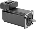
Stepper Servomotors with Integrated Drive
 |
Overall | Shaft | No. of Inputs/Outputs | ||||||||||||||||||
|---|---|---|---|---|---|---|---|---|---|---|---|---|---|---|---|---|---|---|---|---|
Max. Holding Torque, in·ozf | Max. Rotation Speed, rpm | Voltage, V DC | Current, amp | Step Resolution | Full Step Increment | Lg. | Wd. | Ht. | Dia. | Lg. | Ctr.-to-Base Lg. | Control Communication Protocol | Digital Inputs | Analog Inputs | Digital Outputs | Enclosure Rating | Each | |||
NEMA 23 Frame Size | ||||||||||||||||||||
| 142 | 3,000 | 12 to 70 | 3 | 1 to 1/256 | 1.8° | 4.4" | 2.3" | 3.2" | 1/4" | 3/4" | 1.1" | Modbus TCP/IP | 3 | 1 | 1 | IP20 | 5361N17 | 000000000 | ||
| 212 | 3,000 | 12 to 70 | 3 | 1 to 1/256 | 1.8° | 5.3" | 2.3" | 3.2" | 1/4" | 3/4" | 1.1" | Modbus TCP/IP | 3 | 1 | 1 | IP20 | 5361N18 | 00000000 | ||
DC Servomotors with Integrated Drive
 |
A built-in drive simplifies your servomotor setup, removing the need for cable between the motor and drive. DC servomotors are often used for small automation applications, such as pick-and-place machines, because they deliver lots of power in a small package. This system includes a motor, encoder, and drive for accurate positioning and fine control over speed and position.
These servomotors use the same step and direction commands as a stepper motor, so you can upgrade your current stepper motor system with this system. Use a computer to set up and calibrate the motor to your system. After initial setup, use a separate controller, such as a programmable logic controller (PLC), microcontroller, or indexer. The encoder relays distance, direction, and speed back to the servomotor. Based on this feedback, the servomotor dynamically adapts its movements to increase system efficiency.
Maximum Torque—Torque generally decreases as speed increases. Use a torque-speed curve to confirm which motor will work for your application. Click on a part number and select "Product Detail" to view the curve for a motor.
Servomotors | Servomotor Input/Output Cords | Servomotor Power Cords | ||||||||||||||||||
|---|---|---|---|---|---|---|---|---|---|---|---|---|---|---|---|---|---|---|---|---|
Overall | Shaft | |||||||||||||||||||
Max. Torque, in·lbf | Continuous Torque, in·lbf | Max. Rotation Speed, rpm | Wattage, W | Voltage, V DC | Lg. | Wd. | Ht. | Dia. | Lg. | No. of Counts per Rev. | Driver Control Mode | Enclosure Rating | Each | Each | Each | |||||
NEMA 23 Frame Size | ||||||||||||||||||||
| 18.1 | 3.6 | 4,000 | 120 | 75 | 4.1" | 2.3" | 3.2" | 1/4" | 3/4" | 6,400 | Step and Direction | IP53 | 5151N111 | 0000000 | 5151N102 | 000000 | 5151N103 | 000000 | ||
| 30.8 | 6.1 | 3,170 | 173 | 75 | 4.9" | 2.3" | 3.2" | 1/4" | 3/4" | 6,400 | Step and Direction | IP53 | 5151N121 | 000000 | 5151N102 | 00000 | 5151N103 | 00000 | ||
 |
Overall | ||||||||
|---|---|---|---|---|---|---|---|---|
For Motor Voltage, V DC | Operating Voltage, V AC | Lg. | Wd. | Ht. | Cord Lg., ft. | Each | ||
| 75 | 120 | 5.2" | 2.3" | 7.2" | 6 | 5151N21 | 0000000 | |
Dry-Running Electric Slides for Stepper Motors
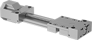 |
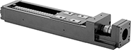
With PTFE sleeve bearings and a low-friction ball screw, these slides don’t require the mess and maintenance of lubrication but still give you precise positioning anywhere along the length of their stroke. Because they have sleeve bearings, they have fewer moving parts, so they perform better in dusty and wet environments than slides with ball bearings. They’re also better at handling impact and vibration.
All slides require a stepper motor, driver, and controller (not included) to operate. As part of this system, they move in precise increments, like the head on an inkjet printer. These electric slides work well for automated assemblies and other applications that require fine, repeatable motion control.
Travel Distance per Turn—Travel distance per turn, also known as screw lead, is how far the carriage moves with one rotation of the ball screw.
Dynamic Load Cap. | For Max. Motor | Overall, mm | Carriage | |||||||||||||||||
|---|---|---|---|---|---|---|---|---|---|---|---|---|---|---|---|---|---|---|---|---|
Stroke Lg., mm | Horiz. | Vert. | Static Load Cap., lb. | Max. Speed, mm/s | Travel Distance per Turn, mm | Repeatability, mm | For Shaft Dia. | Speed, rpm | Torque, in·ozf | Lg. | Wd. | Ht. | Lg., mm | Wd., mm | Bearing Type | Base Material | Each | |||
For NEMA 23 Motor Frames | ||||||||||||||||||||
| 100 | Not Rated | Not Rated | 630 | 50 | 2 | -0.1 to 0.1 | 1/4" | 1,500 | 283 | 277 | 74 | 56 | 69 | 73 | Plain | Aluminum | 6650N12 | 0000000 | ||
| 200 | Not Rated | Not Rated | 630 | 50 | 2 | -0.1 to 0.1 | 1/4" | 1,500 | 283 | 377 | 74 | 56 | 69 | 73 | Plain | Aluminum | 6650N14 | 000000 | ||
| 300 | Not Rated | Not Rated | 630 | 50 | 2 | -0.1 to 0.1 | 1/4" | 1,500 | 283 | 477 | 74 | 56 | 69 | 73 | Plain | Aluminum | 6650N16 | 000000 | ||
| 400 | Not Rated | Not Rated | 630 | 50 | 2 | -0.1 to 0.1 | 1/4" | 1,500 | 283 | 577 | 74 | 56 | 69 | 73 | Plain | Aluminum | 6650N18 | 000000 | ||
| 500 | Not Rated | Not Rated | 630 | 50 | 2 | -0.1 to 0.1 | 1/4" | 1,500 | 283 | 677 | 74 | 56 | 69 | 73 | Plain | Aluminum | 6650N21 | 000000 | ||
| 600 | Not Rated | Not Rated | 630 | 50 | 2 | -0.1 to 0.1 | 1/4" | 1,500 | 283 | 777 | 74 | 56 | 69 | 73 | Plain | Aluminum | 6650N23 | 000000 | ||
Electric Slides for Stepper Motors
 |
Dynamic Load Cap., lb. | For Max. Motor | Overall, mm | Carriage | ||||||||||||||||
|---|---|---|---|---|---|---|---|---|---|---|---|---|---|---|---|---|---|---|---|
Stroke Lg., mm | Horiz. | Vert. | Max. Speed, mm/s | Travel Distance per Turn, mm | Repeatability, mm | For Shaft Dia. | Speed, rpm | Torque, in·ozf | Lg. | Wd. | Ht. | Lg., mm | Wd., mm | Bearing Type | Base Material | Each | |||
For NEMA 23 Motor Frames | |||||||||||||||||||
| 100 | 402 | 402 | 470 | 6 | -0.01 to 0.01 | 1/4" | 4,700 | 176 | 280 | 60 | 56.4 | 76 | 37.4 | Ball | Steel | 6734K812 | 000000000 | ||
| 200 | 402 | 402 | 470 | 6 | -0.01 to 0.01 | 1/4" | 4,700 | 176 | 380 | 60 | 56.4 | 76 | 37.4 | Ball | Steel | 6734K814 | 00000000 | ||
| 300 | 395 | 395 | 790 | 10 | -0.01 to 0.01 | 1/4" | 6,000 | 176 | 480 | 60 | 56.4 | 76 | 37.4 | Ball | Steel | 6734K815 | 00000000 | ||
| 400 | 395 | 395 | 790 | 10 | -0.01 to 0.01 | 1/4" | 5,880 | 176 | 580 | 60 | 56.4 | 76 | 37.4 | Ball | Steel | 6734K816 | 00000000 | ||
| 500 | 395 | 395 | 650 | 10 | -0.01 to 0.01 | 1/4" | 3,900 | 176 | 680 | 60 | 56.4 | 76 | 37.4 | Ball | Steel | 6734K817 | 00000000 | ||
| 600 | 395 | 395 | 470 | 10 | -0.01 to 0.01 | 1/4" | 2,820 | 176 | 780 | 60 | 56.4 | 76 | 37.4 | Ball | Steel | 6734K818 | 00000000 | ||
Stepper Servomotors
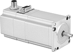 |
Combine the high torque at low speeds that traditional stepper motors are known for with the greater torque performance and positioning reliability of a servomotor. They create rotary motion based on signals from a drive (sold separately). As these servomotors move, their encoder relays the shaft’s distance, direction, and speed back to the drive. The drive increases your system’s efficiency by taking the electrical signal from the encoder and dynamically adapting the motor’s movements, also accounting for inconsistent loads and unexpected forces.
Maximum Holding Torque—Holding torque is the force needed to move the shaft out of position when it is stationary. Torque generally decreases as speed increases. Use a torque-speed curve to confirm which motor will work for your application. Click on a part number and select "Product Detail" to view the curve for a motor.
Servomotors | Servomotor Encoder Cords | Servomotor Power Cords | ||||||||||||||||
|---|---|---|---|---|---|---|---|---|---|---|---|---|---|---|---|---|---|---|
Overall | Shaft | |||||||||||||||||
Max. Holding Torque, in·ozf | Max. Rotation Speed, rpm | Voltage, V DC | Full Step Increment | Lg. | Wd. | Ht. | Dia. | Lg. | Ctr.-to-Base Lg. | Enclosure Rating | Each | Each | Each | |||||
NEMA 23 Frame Size | ||||||||||||||||||
| 113.3 | 2,720 | 48 | 1.8° | 4.8" | 2.3" | 2.7" | 1/4" | 3/4" | 1.11" | IP54 | 5203N12 | 0000000 | 5203N103 | 0000000 | 5203N101 | 0000000 | ||
| 198.3 | 1,940 | 48 | 1.8° | 5.7" | 2.3" | 2.7" | 1/4" | 3/4" | 1.11" | IP54 | 5203N13 | 000000 | 5203N103 | 000000 | 5203N101 | 000000 | ||
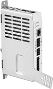 |
Drives have several control modes that power the motor—sequencing, position, speed, or torque. You can program target positions with speeds and accelerations in the drive to trigger sequences with minimal input from a controller. You can also use a computer, programmable logic controller (PLC), microcontroller, or indexer to set motion parameters, tune the motor to your mechanical system, and stream multiple commands to the driver to carry out complex motion sequences.
Overall | No. of Inputs/Outputs | |||||||||||
|---|---|---|---|---|---|---|---|---|---|---|---|---|
Max. Current per Phase, amp | Control Communication Protocol | Operating Voltage, V DC | Lg. | Wd. | Ht. | Inputs | Outputs | Enclosure Rating | Each | |||
For 48V DC Motor Voltage | ||||||||||||
| 20 | EtherCAT, Modbus TCP/IP, EtherNet/IP, PROFINET | 24 to 48 | 5.2" | 1.1" | 6.7" | 2 | 2 | IP20 | 5203N201 | 0000000 | ||
