



























Filter by
Actuator Style


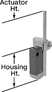
Actuator Height
Electrical Connection Type

Switch Starting Position

Housing Material
Wire Connection

Switch Action
U.S.–Mexico–Canada Agreement (USMCA) Qualifying
Export Control Classification Number (ECCN)
DFARS Specialty Metals
Limit Switches
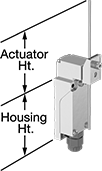 |
Style F |
When a moving object contacts the actuator on these switches, they open or close a circuit. They have the rapid-closing action of a snap-acting switch, but with a larger actuator. This makes them a good choice for use with large objects—for instance, a box on a conveyor runs into the switch, stopping the conveyor.
Rod Actuator—Switches with a rod actuator use a rod extending out of the body to actuate, so they’ll activate even if an object is far away.
Style F—Styles E and F let you adjust the actuator’s height to align it with your target.
NEMA 13 Enclosure Rating—Switches rated NEMA 13 are protected against dirt and oil/coolant spraying.
IP67 Enclosure Rating—Switches rated IP67 are protected against dust and temporary submersion.
Housing | |||||||||||||||||||||
|---|---|---|---|---|---|---|---|---|---|---|---|---|---|---|---|---|---|---|---|---|---|
Style | No. of Circuits Controlled | Switch Starting Position | Switch Action | Switch Designation | Switching Current @ Voltage | Max. Voltage | Actuation Torque, in·ozf | Operating Temp. Range, ° F | Actuator Ht. | For Max. Cable OD | No. of Terminals | Lg. | Ht. | Dp. | Housing Material | Conduit Trade Size | Enclosure Rating | Each | |||
Rod Actuator | |||||||||||||||||||||
Screw-Terminal Wire Connection | |||||||||||||||||||||
| F | 1 | 1 Off or 1 On | Momentary | SPDT | 0.5 amp @ 380V AC, 0.05 amp @ 220V DC | 380V AC 220V DC | — | -4 to 158 | 1.5" to 5" | 0.25" | 4 | 1.1" | 2.5" | 1" | Zinc | — | NEMA 13, IP67 | 7988K3 | 000000 | ||
| F | 1 | 1 Off or 1 On | Momentary | SPDT | 10 amp @ 240V AC, 10 amp @ 24V DC | 600V AC 250V DC | — | 10 to 250 | 0.5" to 4.3" | — | 4 | 1.9" | 4.5" | 1.8" | Zinc | 1/2 | NEMA 6P, NEMA 13, IP66, IP67 | 65785K15 | 000000 | ||
| F | 1 | 1 Off or 1 On | Momentary | SPDT | 10 amp @ 300V AC, 6 amp @ 24V DC | 300V AC 250V DC | 50.6 | 14 to 176 | 1.4" to 5.9" | — | 4 | 1.6" | 2.7" | 1.6" | Aluminum | 1/2 | IP67 | 7076K24 | 000000 | ||
| F | 2 | 2 Off or 2 On | Momentary | DPDT | 5 amp @ 240V AC, 10 amp @ 24V DC | 600V AC 250V DC | — | 10 to 250 | 0.5" to 11.8" | — | 8 | 1.9" | 4.5" | 1.8" | Zinc | 1/2 | NEMA 6P, NEMA 13, IP66, IP67 | 65785K76 | 000000 | ||
Safety Limit Switches
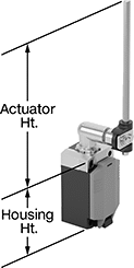 |
Style F |
Protect machinery and ensure the safety of personnel—these switches have positive-force contacts that will open the circuit when actuated even if a spring fails or the contacts stick. When an object in motion comes into contact with the actuator, it sends a signal to open or close a circuit. These switches have the rapid-closing action of a snap-acting switch, but with a larger actuator. This makes them a good choice for use with large objects—for instance, a box on a conveyor runs into the switch, stopping the conveyor.
Rod Actuator—Switches with a rod actuator use a rod extending out of the body to actuate, so they’ll activate even if an object is far away.
Style F—Styles D, E, and F have an actuator that allows you to adjust its height, making it easier to align switch with the target during installation.
Steel Actuator—Switches with a steel actuator are more durable than switches with a plastic actuator. They also handle higher loads.
Housing | |||||||||||||||||||||
|---|---|---|---|---|---|---|---|---|---|---|---|---|---|---|---|---|---|---|---|---|---|
Style | No. of Circuits Controlled | Switch Starting Position | Switch Action | Switch Designation | Actuator Material | Switching Current @ Voltage | Max. Voltage | Actuation Torque, in·ozf | Operating Temp. Range, ° F | Actuator Ht. | No. of Terminals | Lg. | Ht. | Dp. | Housing Material | Conduit Thread Size | Enclosure Rating | Each | |||
Rod Actuator | |||||||||||||||||||||
Screw-Terminal Wire Connection | |||||||||||||||||||||
| F | 1 | 1 Off or 1 On | Momentary | SPDT | Steel | 3 amp @ 240V AC, 1.5 amp @ 24V DC | 240V AC 24V DC | 24.8 | -22 to 165 | 0.5" to 8" | 4 | 1.7" | 2.9" | 1.6" | Plastic | M20 | NEMA 4X, IP66, IP67 | 65745K46 | 0000000 | ||
Compact Safety Limit Switches
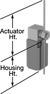 |
Style F |
Shorter and thinner than other safety limit switches, these are sized to fit tight spaces. They protect machinery and ensure the safety of personnel. Positive-force contacts open the circuit when actuated, even if a spring fails or the contacts stick. They send a signal to your circuit when an object hits the actuator—for instance, a box on a conveyor runs into the switch, stopping the conveyor. They open and close circuits as fast as snap-acting switches, but they have a bigger actuator for large objects. All are NEMA and IP rated for protection from washdowns.
Rod Actuator—Switches with a rod actuator have a large actuation area with a rod extending out of the actuator’s body. They’re best where the object actuating the switch is far away.
Style F—Styles E and F have an actuator that allows you to adjust its height, making it easier to align the switch with the target during installation.
NEMA 13 Enclosure Rating and IP67 Enclosure Rating—NEMA 13 and IP67 rated switches are protected from oil/coolant spraying and temporary submersion.
Housing | ||||||||||||||||||||
|---|---|---|---|---|---|---|---|---|---|---|---|---|---|---|---|---|---|---|---|---|
Style | No. of Circuits Controlled | Switch Starting Position | Switch Action | Switch Designation | Switching Current @ Voltage | Max. Voltage | Actuation Torque, in·ozf | Operating Temp. Range, ° F | Actuator Ht. | No. of Terminals | Lg. | Ht. | Dp. | Housing Material | Conduit Trade Size | Enclosure Rating | Each | |||
Rod Actuator | ||||||||||||||||||||
Screw-Terminal Wire Connection | ||||||||||||||||||||
| F | 1 | 1 Off or 1 On | Momentary | SPDT | 10 amp @ 600V AC, 10 amp @ 250V DC | 600V AC 250V DC | 17.6 | -40 to 185 | 0.6" to 5.8" | 4 | 1.2" | 2.4" | 1.2" | Plastic | 1/2 | NEMA 4, NEMA 13, IP66, IP67 | 65745K18 | 000000 | ||
Build-Your-Own Limit Switches
 |
Style J |
Combine an actuator and a switch to assemble the exact limit switch you need. These switches have the rapid-closing action of a snap-acting switch, but have a larger actuator for large objects. When an object in motion comes into contact with the actuator, it sends a signal to open or close a circuit. They’re often used for conveyor systems and elevators. Each actuator style is compatible with all housing styles and vice versa.
Washdown Limit Switches
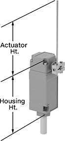 |
Style E |
Rated NEMA 3S and IP69K, these switches can handle washdowns with high pressures and temperatures. They’re also protected from oil/coolant spraying, precipitation, and temporary submersion. When an object in motion contacts the actuator, it sends a signal to open or close a circuit. These switches have the rapid-closing action of a snap-acting switch, but with a larger actuator. This makes them a good choice for use with large objects—for instance, a box on a conveyor runs into the switch, stopping the conveyor.
Rod Actuator—Switches with a rod actuator use a rod extending out of the body to actuate, so they’ll activate even if an object is far away.
Style E—Styles D, E, and F let you adjust the actuator’s height to align it with your target.
Housing | ||||||||||||||||||||
|---|---|---|---|---|---|---|---|---|---|---|---|---|---|---|---|---|---|---|---|---|
Style | No. of Circuits Controlled | Switch Starting Position | Switch Action | Switch Designation | Switching Current @ Voltage | Max. Voltage | Actuation Torque, in·ozf | Operating Temp. Range, ° F | Actuator Ht. | No. of Wire Leads | Cable Lead Lg., ft. | Lg. | Ht. | Dp. | Housing Material | Enclosure Rating | Each | |||
Rod Actuator | ||||||||||||||||||||
Wire Lead Connection | ||||||||||||||||||||
| E | 1 | 1 Off or 1 On | Momentary | SPDT | 10 amp @ 240V AC, 1 amp @ 250V DC | 240V AC 250V DC | 0.92 | 10 to 200 | 0" to 5.5" | 5 | 8 | 1.5" | 4.6" | 1.6" | Zinc | NEMA 3S, NEMA 6P, NEMA 13, IP67, IP69K | 7926K155 | 0000000 | ||
| E | 2 | 2 Off or 2 On | Momentary | DPDT | 10 amp @ 240V AC, 1 amp @ 250V DC | 240V AC 250V DC | 0.92 | 10 to 200 | 0" to 5.5" | 5 | 8 | 1.5" | 4.6" | 1.6" | Zinc | NEMA 3S, NEMA 6P, NEMA 13, IP67, IP69K | 7926K156 | 00000000 | ||
Wireless Self-Powered Limit Switches
 |
Style E |
Install these limit switches where changing a battery or routing wires might be difficult—they power themselves when a moving object contacts the actuator. Place them up to 330 ft. away from the receiver (sold separately). These switches have the rapid-closing action of a snap-acting switch, but with a larger actuator.
Rod Actuator—Rod actuators open or close circuits when material pushes against the rod. The rod extends from the body of the actuator, so these switches are ideal when objects actuating the switch are further away.
Housing | |||||||||||||||||
|---|---|---|---|---|---|---|---|---|---|---|---|---|---|---|---|---|---|
Style | No. of Circuits Controlled | Max. Transmission Distance, ft. | Transmission Freq., MHz | Switch Action | Actuator Material | Operating Temp. Range, ° F | Actuator Ht. | Lg. | Ht. | Dp. | Housing Material | Certification | Specs. Met | Each | |||
Rod Actuator | |||||||||||||||||
| E | 1 | 330 | 2,405 | Momentary | Plastic | -13 to 131 | 3" | 1.2" | 2.5" | 0.6" | Plastic | CE Marked | IEC 60947-5, EN 60947-5 | 7786N18 | 0000000 | ||
 |
No. of Outputs | Max. Transmission Distance, ft. | Transmission Freq., MHz | Max. Switching Current @ Voltage | Input Voltage, V DC | Output Digital Signal | Mounting Location | For DIN Rail Size, mm | Wd. | Ht. | Dp. | Enclosure Rating | Certification | Specs. Met | Each | |||
|---|---|---|---|---|---|---|---|---|---|---|---|---|---|---|---|---|---|
Screw-Terminal Wire Connection | |||||||||||||||||
| 2 | 330 | 2,405 | 200 mA @ 24V DC | 24 | PNP | DIN Rail | 35 | 1 7/16" | 4 1/4" | 2 15/16" | IP20 | CE Marked | IEC 60947-5-1, IEC 60947-1, EN 60947-5-1, EN 60947-1 | 7786N19 | 0000000 | ||
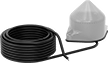 |
Use an antenna to increase the maximum transmission range to 984 ft. They also strengthen the signal if there are obstacles between your switch and receiver.
Max. Transmission Distance, ft. | Transmission Freq., MHz | Input Voltage | Cable Lg., ft. | Enclosure Rating | Certification | Each | |||
|---|---|---|---|---|---|---|---|---|---|
Wire Lead Connection | |||||||||
| 984 | 2,405 | 24V AC to 240V AC, 24V DC to 240V DC | 16 | IP65 | UL Listed, CSA Certified, CE Marked | 7786N11 | 0000000 | ||
Single-Action Mechanically Operated Air Directional Control Valves
 |
Style M |
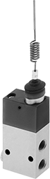
A simple automation solution that requires no programming, these valves are activated when an object, such as a box rolling on a conveyor, pushes the actuator. Also known as 3-way and 3/2 valves, they create one action, such as extending a cylinder. Valves direct airflow from the inlet to your equipment and exhaust return airflow to create motion. Return actuation is by spring, so they go back to their starting position as soon as the actuator is released. In the off position, they exhaust air pressure from the system, allowing equipment to reset so the action can be repeated.
Threaded Female Inlet x Threaded Female Outlet
|
Style M |
2-Direction Actuation—Valves with a two-direction actuator are activated by objects from both sides.
Valve Position—Fail-closed valves block airflow until actuated. Valves that are both fail closed and fail open can be installed to block airflow, or allow air to flow until actuated.
Flow Coefficient (Cv)—Flow coefficient (Cv) is a measurement that indicates how much airflow can pass through a valve. When selecting between valves with the same port size, choose the valve with the higher flow coefficient to ensure it provides enough airflow to operate your system.
Overall, mm | ||||||||||||||||||
|---|---|---|---|---|---|---|---|---|---|---|---|---|---|---|---|---|---|---|
Style | Actuation Force, lbf | No. of Flow Ports | Inlet Size | Outlet Size | Exhaust Connection | Max. Flow Rate @ 100 psi, scfm | Flow Coefficient (Cv) | Pressure Range, psi | Vacuum Rating | Lg. | Wd. | Ht. | For Panel Cutout Dia., mm | Mounting Fasteners Included | Each | |||
2-Direction Actuation | ||||||||||||||||||
Fail Closed | ||||||||||||||||||
| M | 1.57 | 3 | 1/8 BSPP | 1/8 BSPP | Threaded | 4.23 | 0.12 | 53 to 120 | Not Rated | 36 | 18 | 220 | 19 | No | 6464K92 | 0000000 | ||
Two-Speed Two-Action Mechanically Operated Air Directional Control Valves
 |
Style K |
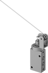
Often used to extend and then retract a cylinder at different speeds, these valves create two actions and have two exhaust ports, which allows you to control the speed of each action by attaching a flow control valve to each exhaust port. A simple automation solution that requires no programming, they activate when an object, such as a box rolling on a conveyor, pushes the actuator. They direct airflow from the inlet to your equipment and exhaust return airflow to create motion. Return actuation is by spring, so they go back to their original position as soon the actuator is released. Also known as 4-way and 5/2 valves.
2-Direction Actuation—Valves with a two-direction actuator are activated by objects from both sides.
NPTF Inlet Thread—NPTF (Dryseal) threads are compatible with NPT threads.
Flow Coefficient (Cv)—Flow coefficient (Cv) indicates how much airflow can pass through a valve.
Overall | For Panel Cutout | ||||||||||||||||||||
|---|---|---|---|---|---|---|---|---|---|---|---|---|---|---|---|---|---|---|---|---|---|
Style | Actuation Force, lbf | No. of Flow Ports | Inlet Size | Outlet Size | Exhaust Connection | Max. Flow Rate @ 100 psi, scfm | Flow Coefficient (Cv) | Pressure Range, psi | Vacuum Rating | Lg. | Wd. | Ht. | Mount Type | Wd. | Lg. | Mounting Fasteners Included | Mounting Hole Dia. | Each | |||
Threaded Female Inlet x Threaded Female Outlet | |||||||||||||||||||||
2-Direction Actuation—Spring Return | |||||||||||||||||||||
| K | 0.3 | 5 | 1/8 NPTF | 1/8 NPTF | Threaded | 14 | 0.24 | 25 to 125 | Not Rated | 6 1/4" | 3/4" | 3 7/8" | Panel, Screw In | 3/4" | 1 1/4" | No | 0.19" | 61345K14 | 0000000 | ||
