


Filter by
Actuator Style


Switch Action
Position Designation
System of Measurement
Switching Voltage
Illumination
Push-Button Shape

Mount Type

Mounting Location
Wire Connection
Switch Starting Position
Panel Cutout Diameter
Enclosure Rating
DFARS Specialty Metals
Export Control Classification Number (ECCN)

About Electrical Switches
Choose a switch with the right trigger type, number of inputs, and control functions to power your equipment.
Rocker Switches
 |  |
Style A | Style D |
The wide surface of these switches makes them easy to press on and off, even if your hands are full and you need to use an elbow. They’re often used as power switches on electronic devices and control panels.
Note: Illuminated switches include a bulb. If wiring the switch and the bulb to the same circuit, the circuit voltage must not exceed the bulb voltage.
Illuminated—Illuminated switches are easy to see in dim and dark areas. They come in red and green, so you can color code your set up.
For 13/16" Diameter Panel Cutouts—Switches for a 13/16” dia. panel cutout are round, so you can use a drill bit or knockout to install them instead of cutting a rectangular hole.
On-On—Switches with an on-on position designation alternate power between sets of terminals.
Style | No. of Circuits Controlled | Switch Starting Position | Switch Action | No. of Terminals | Switch Designation | Position Designation | Switching Current @ Voltage | Max. Voltage, V AC | Bulb Voltage, V AC | Quick-Disconnect Tab Wd. | Bulb Type | Choose a Color | Each | |||
|---|---|---|---|---|---|---|---|---|---|---|---|---|---|---|---|---|
2 Positions with Quick-Disconnect Terminals | ||||||||||||||||
For 13/16" Diameter Panel Cutouts | ||||||||||||||||
| A | 1 | 1 Off | Maintained | 3 | SPST-NO | On-On | 10 amp @ 125V AC | 125 | — | 0.189" | — | Black | 7395K127 | 00000 | ||
| A | 1 | 1 Off | Maintained | 3 | SPST-NO | On-On | 16 amp @ 125V AC, 10 amp @ 250V AC | 250 | — | 0.189" | — | Black | 7395K129 | 0000 | ||
| A | 1 | 1 On | Maintained | 2 | SPST-NC | On-Off | 10 amp @ 125V AC | 125 | — | 0.189" | — | Black | 7395K126 | 0000 | ||
| A | 1 | 1 On | Maintained | 2 | SPST-NC | On-Off | 16 amp @ 125V AC, 10 amp @ 250V AC | 250 | — | 0.189" | — | Black | 7395K128 | 0000 | ||
2 Positions with Quick-Disconnect Terminals—Illuminated | ||||||||||||||||
For 13/16" Diameter Panel Cutouts | ||||||||||||||||
| D | 1 | 1 On | Maintained | 3 | SPST-NC | On-Off | 16 amp @ 125V AC, 10 amp @ 250V AC | 250 | 125 | 0.189" | Neon | Green, Red | 7395K103 | 0000 | ||
3 Positions with Quick-Disconnect Terminals | ||||||||||||||||
For 13/16" Diameter Panel Cutouts | ||||||||||||||||
| A | 1 | 1 Off | Maintained | 3 | SPST-NO | On-Off-On | 16 amp @ 125V AC, 10 amp @ 250V AC | 250 | — | 0.189" | — | Black | 7395K135 | 0000 | ||
Limit Switches
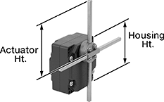 |
Style G |
When a moving object contacts the actuator on these switches, they open or close a circuit. They have the rapid-closing action of a snap-acting switch, but with a larger actuator. This makes them a good choice for use with large objects—for instance, a box on a conveyor runs into the switch, stopping the conveyor.
T-Rod Actuator—Switches with a T-rod actuator have four rods extending in different directions from a pivot point. If an object contacts any of the rods from any direction, these switches actuate. Since they have such a large actuation area, they’re great for detecting moving parts when your machine tool isn’t perfectly aligned.
Housing | |||||||||||||||||||
|---|---|---|---|---|---|---|---|---|---|---|---|---|---|---|---|---|---|---|---|
Style | No. of Circuits Controlled | Switch Starting Position | Switch Action | Switch Designation | Switching Current @ Voltage | Max. Voltage | Operating Temp. Range, ° F | Actuator Ht. | No. of Terminals | Lg. | Ht. | Dp. | Housing Material | Conduit Thread Size | Enclosure Rating | Each | |||
T-Rod Actuator | |||||||||||||||||||
Screw-Terminal Wire Connection | |||||||||||||||||||
| G | 2 | 2 Off or 2 On | Maintained | DPDT | 10 amp @ 240V AC, 0.27 amp @ 250V DC | 240V AC 250V DC | -13 to 158 | 7.9" | 8 | 3.4" | 3.7" | 2.1" | Zinc | PG-13.5 | IP54 | 7988K106 | 0000000 | ||
Differential Pressure Switches for Air
 |
Connects to Tube |
Often used with ovens, dryers, and HVAC systems, these switches detect small differences in air pressure to indicate a filter is clogged or help you maintain a certain air pressure. When the differential pressure reaches your setpoint, these switches can turn equipment on and off, activate automated controls, or signal alarms. They are single pole, double throw (SPDT) and can be installed to turn one circuit from off to on or from on to off. All meet at least one safety standard.
When measuring pressure in ductwork, pair them with a static pressure probe.
IP54 Enclosure Rating—Switches rated IP54 protect against dust and splashing water.
NEMA 13 Enclosure Rating— NEMA 13 rated switches can be used in dirty, wet, and oily areas.
Pressure Set Point, in. H₂O | Approx. Difference Between Set Point and Reset Point, in. H₂O | Max. Input Pressure, in. H₂O | Accuracy | Max. Switching Current @ Voltage | Process Temp. Range, ° F | Connection Material | For Use With | Certification | Enclosure Rating | Each | |||
|---|---|---|---|---|---|---|---|---|---|---|---|---|---|
Screw-Terminal Wire Connection | |||||||||||||
1/4" Barbed Male Tube Connection | |||||||||||||
| 0.08 to 1.2 | 0.05 | 40 | ±1% | 1.5 amp @ 120V AC 400 mA @ 250V AC | 0 to 185 | Nylon | Air | C-ETL Listed, ETL Listed | IP54, NEMA 13 | 3964N11 | 000000 | ||
| 0.12 to 1.6 | 0.08 | 40 | ±1% | 1.5 amp @ 120V AC 400 mA @ 250V AC | 0 to 185 | Nylon | Air | C-ETL Listed, ETL Listed | IP54, NEMA 13 | 3964N12 | 00000 | ||
| 0.2 to 2 | 0.09 | 40 | ±1% | 1.5 amp @ 120V AC 400 mA @ 250V AC | 0 to 185 | Nylon | Air | C-ETL Listed, ETL Listed | IP54, NEMA 13 | 3964N13 | 00000 | ||
| 0.8 to 4 | 0.45 | 40 | ±1% | 1.5 amp @ 120V AC 400 mA @ 250V AC | 0 to 185 | Nylon | Air | C-ETL Listed, ETL Listed | IP54, NEMA 13 | 3964N14 | 00000 | ||
| 2 to 10 | 0.7 | 40 | ±1% | 1.5 amp @ 120V AC 400 mA @ 250V AC | 0 to 185 | Nylon | Air | C-ETL Listed, ETL Listed | IP54, NEMA 13 | 3964N15 | 00000 | ||
| 4 to 20 | 1.2 | 40 | ±1% | 1.5 amp @ 120V AC 400 mA @ 250V AC | 0 to 185 | Nylon | Air | C-ETL Listed, ETL Listed | IP54, NEMA 13 | 3964N16 | 00000 | ||
Hazardous Location Differential Pressure Switches for Air
 |
With an explosion-proof enclosure that meets NEMA 7 and 9 standards for hazardous locations, these switches were tested and verified by UL for use where explosive gas or dust may be present. Often used with ovens, dryers, and HVAC systems, they can indicate a filter is clogged or help maintain a certain air pressure. These switches turn equipment on and off, activate automated controls, or signal alarms when the differential pressure reaches your setpoint. They are single pole, double throw (SPDT) and can be installed to turn one circuit from off to on or from on to off.
In addition to being UL listed, these switches are CE marked and FM approved, so they also meet European safety standards. They also are IP and NEMA rated for use outdoors and protect against dust and splashing water.
When measuring pressure in ductwork, pair them with a static pressure probe.
Pressure Set Point Range | Approx. Difference Between Set Point and Reset Point | Max. Input Pressure | Accuracy | Max. Switching Current @ Voltage | Process Temp. Range, ° F | Connection Material | For Use With | Enclosure Rating | Hazardous Location Rating | Each | |||
|---|---|---|---|---|---|---|---|---|---|---|---|---|---|
Screw-Terminal Wire Connection | |||||||||||||
1/8 NPT Female Pipe Connection | |||||||||||||
| 0.07 in. H₂O to 0.15 in. H₂O | 0.13 in. H₂O | 45 in. H₂O | ±2% | 15 amp @ 125V AC 15 amp @ 250V AC 15 amp @ 480V AC | -40 to 140 | Aluminum | Air | IP54, NEMA 3, NEMA 7, NEMA 9 | NEC Class I Divisions 1, 2 Groups C, D; NEC Class II Divisions 1, 2 Groups E, F, G | 5114N11 | 0000000 | ||
| 0.15 in. H₂O to 0.5 in. H₂O | 0.05 in. H₂O | 45 in. H₂O | ±2% | 15 amp @ 125V AC 15 amp @ 250V AC 15 amp @ 480V AC | -40 to 140 | Aluminum | Air | IP54, NEMA 3, NEMA 7, NEMA 9 | NEC Class I Divisions 1, 2 Groups C, D; NEC Class II Divisions 1, 2 Groups E, F, G | 5114N12 | 000000 | ||
| 0.4 in. H₂O to 1.6 in. H₂O | 0.18 in. H₂O | 45 in. H₂O | ±2% | 15 amp @ 125V AC 15 amp @ 250V AC 15 amp @ 480V AC | -40 to 140 | Aluminum | Air | IP54, NEMA 3, NEMA 7, NEMA 9 | NEC Class I Divisions 1, 2 Groups C, D; NEC Class II Divisions 1, 2 Groups E, F, G | 5114N13 | 000000 | ||
| 1.4 in. H₂O to 5.5 in. H₂O | 0.35 in. H₂O | 45 in. H₂O | ±2% | 15 amp @ 125V AC 15 amp @ 250V AC 15 amp @ 480V AC | -40 to 140 | Aluminum | Air | IP54, NEMA 3, NEMA 7, NEMA 9 | NEC Class I Divisions 1, 2 Groups C, D; NEC Class II Divisions 1, 2 Groups E, F, G | 5114N14 | 000000 | ||
| 3 in. H₂O to 11 in. H₂O | 0.45 in. H₂O | 45 in. H₂O | ±2% | 15 amp @ 125V AC 15 amp @ 250V AC 15 amp @ 480V AC | -40 to 140 | Aluminum | Air | IP54, NEMA 3, NEMA 7, NEMA 9 | NEC Class I Divisions 1, 2 Groups C, D; NEC Class II Divisions 1, 2 Groups E, F, G | 5114N15 | 000000 | ||
| 4 in. H₂O to 20 in. H₂O | 0.5 in. H₂O | 45 in. H₂O | ±2% | 15 amp @ 125V AC 15 amp @ 250V AC 15 amp @ 480V AC | -40 to 140 | Aluminum | Air | IP54, NEMA 3, NEMA 7, NEMA 9 | NEC Class I Divisions 1, 2 Groups C, D; NEC Class II Divisions 1, 2 Groups E, F, G | 5114N16 | 000000 | ||
| 0.5 psi to 2 psi | 0.3 psi | 35 psi | ±2% | 15 amp @ 125V AC 15 amp @ 250V AC 15 amp @ 480V AC | -40 to 140 | Aluminum | Air | IP54, NEMA 3, NEMA 7, NEMA 9 | NEC Class I Divisions 1, 2 Groups C, D; NEC Class II Divisions 1, 2 Groups E, F, G | 5114N17 | 000000 | ||
| 1.5 psi to 8 psi | 1 psi | 35 psi | ±2% | 15 amp @ 125V AC 15 amp @ 250V AC 15 amp @ 480V AC | 0 to 140 | Aluminum | Air | IP54, NEMA 3, NEMA 7, NEMA 9 | NEC Class I Divisions 1, 2 Groups C, D; NEC Class II Divisions 1, 2 Groups E, F, G | 5114N18 | 000000 | ||
| 3 psi to 15 psi | 0.9 psi | 35 psi | ±2% | 15 amp @ 125V AC 15 amp @ 250V AC 15 amp @ 480V AC | 0 to 140 | Aluminum | Air | IP54, NEMA 3, NEMA 7, NEMA 9 | NEC Class I Divisions 1, 2 Groups C, D; NEC Class II Divisions 1, 2 Groups E, F, G | 5114N19 | 000000 | ||
| 4 psi to 25 psi | 0.7 psi | 35 psi | ±2% | 15 amp @ 125V AC 15 amp @ 250V AC 15 amp @ 480V AC | 0 to 140 | Aluminum | Air | IP54, NEMA 3, NEMA 7, NEMA 9 | NEC Class I Divisions 1, 2 Groups C, D; NEC Class II Divisions 1, 2 Groups E, F, G | 5114N21 | 000000 | ||
| 15 psi to 50 psi | 1.25 psi | 70 psi | ±2% | 15 amp @ 125V AC 15 amp @ 250V AC 15 amp @ 480V AC | 0 to 140 | Aluminum | Air | IP54, NEMA 3, NEMA 7, NEMA 9 | NEC Class I Divisions 1, 2 Groups C, D; NEC Class II Divisions 1, 2 Groups E, F, G | 5114N22 | 000000 | ||
Contactless Flow Transmitters
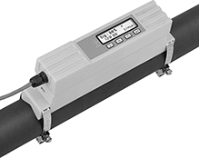 |
Using ultrasonic waves, these transmitters measure the flow rate of your liquid from outside your pipe. They're a good choice for applications where you need to retrofit your system or avoid liquid coming into contact with the transmitter. Also known as transducers, these transmitters convert measurements to an electrical pulse that can be interpreted by receiving devices, such as remote displays and programmable logic controllers (PLCs). The pulse outputs match the input voltage of the transmitter. The higher the flow, the more pulses they send. For your receiving device to interpret the signal, you will need to calibrate it for the measurement range and output signal of the transmitter. They only give accurate readings within the rated measurement range. Configure them for either a 4-20mA or digital pulse output when installing.
A digital display makes it easy to check flow rate and configure settings. Clamp these transmitters onto your pipe with the included mounting hardware and gel pads. They measure flow no matter the mounting orientation.
These transmitters are calibrated with water but can be used with other liquids and will generally measure accurately, even if they differ in viscosity and density. You can recalibrate them in the field for accurate readings on pipe and operating conditions.
Flow Range for Pipe Size, gpm | Input Voltage | |||||||||||||||
|---|---|---|---|---|---|---|---|---|---|---|---|---|---|---|---|---|
Flow Measurement Type | For Pipe Size | 3/4 | 2 | 4 | End-to-End Lg. | Accuracy | Temp. Range, ° F | Min., V DC | Max. | Mounting Position | Field Recalibratable | Enclosure Rating | Each | |||
One Digital Pulse Output and One 4-20 mA Analog Transmitter Output—Wire Lead Connection | ||||||||||||||||
Polycarbonate Body | ||||||||||||||||
| Ultrasonic | 3/4 to 4 | 0 to 45 | 0 to 320 | 0 to 1,285 | 9 3/4" | ±3% | 32 to 185 | 12 | 24V AC/24V DC | Any Angle | Yes | IP54 | 4399N11 | 000000000 | ||
Rocker Switch Covers
 |
For Max. Switch | For Max. Rocker Cutout | ||||||||
|---|---|---|---|---|---|---|---|---|---|
Ht. | Wd. | Ht. | Wd. | Material | Environment | Enclosure Rating | Each | ||
| 0.83" | 0.6" | 0.7" | 0.43" | Rubber | Dusty, Wet | IP54 | 7395K91 | 00000 | |
| 1.09" | 0.73" | 0.95" | 0.61" | Rubber | Dusty, Wet | IP54 | 1730N28 | 0000 | |
| 1.22" | 1" | 1.13" | 0.88" | Rubber | Dusty, Wet | IP54 | 1730N12 | 0000 | |
| 1.22" | 1" | 1.18" | 0.87" | Rubber | Dusty, Wet | IP54 | 1730N22 | 0000 | |
| 1.22" | 1" | 1.19" | 0.88" | Rubber | Dusty, Wet | IP54 | 1730N11 | 0000 | |
| 1.22" | 1" | 1.2" | 0.87" | Rubber | Dusty, Wet | IP54 | 1730N23 | 0000 | |
| 1.25" | 0.55" | 0.99" | 0.36" | Rubber | Dusty, Wet | IP54 | 7395K93 | 0000 | |
| 1.27" | 0.68" | 1.12" | 0.48" | Rubber | Dusty, Wet | IP54 | 1730N24 | 0000 | |
| 1.28" | 0.69" | 0.85" | 0.4" | Rubber | Dusty, Wet | IP54 | 7395K92 | 0000 | |
| 1.72" | 0.97" | 1.25" | 0.75" | Rubber | Dusty, Wet | IP54 | 1730N17 | 0000 | |
| 1.72" | 0.97" | 1.34" | 0.69" | Rubber | Dusty, Wet | IP54 | 1730N21 | 0000 | |
| 1.72" | 0.97" | 1.5" | 0.88" | Rubber | Dusty, Wet | IP54 | 1730N29 | 0000 | |
| 1.79" | 3/4" | 1.1" | 0.52" | Rubber | Dusty, Wet | IP54 | 7395K94 | 0000 | |
| 2.19" | 0.98" | 1.44" | 0.94" | Rubber | Dusty, Wet | IP54 | 1730N18 | 0000 | |
Cable-Pull-Actuator Emergency Stop Switches with Restart Switch
1 Direction
 |  |
Left Side Cable Location | Right Side Cable Location |
Mounting | |||||||||||||||||
|---|---|---|---|---|---|---|---|---|---|---|---|---|---|---|---|---|---|
Cable Location | For Max. Cable Lg., ft. | No. of Circuits Controlled | Switch Starting Position | No. of Terminals | Switch Designation | Switching Current @ Voltage | Max. Voltage | Actuation Force, lbf | Conduit Trade Size | Bulb Voltage | Fasteners Included | No. of Holes | Hole Dia. | Each | |||
Screw-Terminal Wire Connection | |||||||||||||||||
With Emergency Stop Button, Power Indicator, Restart Button, Tension Indicator (IP54, NEMA 1) | |||||||||||||||||
| Left Side | 325 | 2 | 2 Off or 2 On | 6 | DPDT | 6 amp @ 120V AC 2.8 amp @ 24V DC | 240V AC 24V DC | 11 | 1/2 | 24V DC | No | 4 | 1/4" | 5746N301 | 000000000 | ||
| Left Side | 325 | 2 | 2 Off or 2 On | 6 | DPDT | 6 amp @ 120V AC 2.8 amp @ 24V DC | 240V AC 24V DC | 11 | 1/2 | 120V AC | No | 4 | 1/4" | 5746N201 | 00000000 | ||
| Right Side | 325 | 2 | 2 Off or 2 On | 6 | DPDT | 6 amp @ 120V AC 2.8 amp @ 24V DC | 240V AC 24V DC | 11 | 1/2 | 24V DC | No | 4 | 1/4" | 5746N11 | 00000000 | ||
| Right Side | 325 | 2 | 2 Off or 2 On | 6 | DPDT | 6 amp @ 120V AC 2.8 amp @ 24V DC | 240V AC 24V DC | 11 | 1/2 | 120V AC | No | 4 | 1/4" | 5746N202 | 00000000 | ||
2 Directions
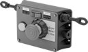 |
Two-direction switches support twice the total cable distance of one-direction switches. With pulls on each side, you can route cable in two opposite directions. These switches are often placed at the midpoint of conveyors and other long runs of equipment.
Mounting | |||||||||||||||||
|---|---|---|---|---|---|---|---|---|---|---|---|---|---|---|---|---|---|
Cable Location | For Max. Cable Lg., ft. | No. of Circuits Controlled | Switch Starting Position | No. of Terminals | Switch Designation | Switching Current @ Voltage | Max. Voltage | Actuation Force, lbf | Conduit Trade Size | Bulb Voltage | Fasteners Included | No. of Holes | Hole Dia. | Each | |||
Screw-Terminal Wire Connection | |||||||||||||||||
With Emergency Stop Button, Power Indicator, Restart Button, Tension Indicator (IP54, NEMA 1) | |||||||||||||||||
| Left Side, Right Side | 325 | 2 | 2 Off or 2 On | 6 | DPDT | 6 amp @ 120V AC 2.8 amp @ 24V DC | 240V AC 24V DC | 11 | 1/2 | 24V DC | No | 4 | 1/4" | 5746N12 | 000000000 | ||
| Left Side, Right Side | 325 | 2 | 2 Off or 2 On | 6 | DPDT | 6 amp @ 120V AC 2.8 amp @ 24V DC | 240V AC 24V DC | 11 | 1/2 | 120V AC | No | 4 | 1/4" | 5746N204 | 00000000 | ||
Blade-Style Circuit Breakers
Automatic Reset
Automatic reset breakers don’t require you to manually reset them after they trip, so they’re good for areas where the breaker isn’t easily accessed. These breakers reset once they cool. However, they will trip repeatedly if the overcurrent condition continues.
Breakthrough Current @ Voltage—Breakthrough current is the maximum current that the circuit breaker can safely stop in the event of a short circuit.
Current, A | Breakthrough Current @ Voltage | Mounting Location | Ht. | Wd. | Blade Ht. | Temp. Range, ° F | Enclosure Rating | Specs. Met | Each | |||
|---|---|---|---|---|---|---|---|---|---|---|---|---|
12V DC | ||||||||||||
| 6 | 2,000 amp @ 12V DC | Fuse Block | 0.95" | 0.79" | 0.25" | -40 to 185 | IP54 | SAE J553 | 4212T11 | 00000 | ||
| 8 | 2,000 amp @ 12V DC | Fuse Block | 0.95" | 0.79" | 0.25" | -40 to 185 | IP54 | SAE J553 | 4212T12 | 0000 | ||
| 10 | 2,000 amp @ 12V DC | Fuse Block | 0.95" | 0.79" | 0.25" | -40 to 185 | IP54 | SAE J553 | 4212T13 | 0000 | ||
| 15 | 2,000 amp @ 12V DC | Fuse Block | 0.95" | 0.79" | 0.25" | -40 to 185 | IP54 | SAE J553 | 4212T14 | 0000 | ||
| 20 | 2,000 amp @ 12V DC | Fuse Block | 0.95" | 0.79" | 0.25" | -40 to 185 | IP54 | SAE J553 | 4212T15 | 0000 | ||
| 25 | 2,000 amp @ 12V DC | Fuse Block | 0.95" | 0.79" | 0.25" | -40 to 185 | IP54 | SAE J553 | 4212T16 | 0000 | ||
| 30 | 2,000 amp @ 12V DC | Fuse Block | 0.95" | 0.79" | 0.25" | -40 to 185 | IP54 | SAE J553 | 4212T17 | 0000 | ||
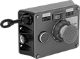
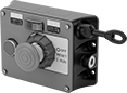
Tablet Holders with Emergency Stop Switch
 | 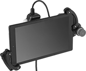 |
Pivoting Handle (Back View) | Holder with Tablet Installed (Not Included) |
 |  |
Holder | Tablet Holder Bracket Kits |
Halt machinery in an instant with these tablet holders. They equip your tablet with safety switches that meet IEC and EN standards, so you can safely move around your equipment while teaching robots or monitoring production lines and conveyor systems.
The emergency stop switch on the front of the holder illuminates when the switch is enabled. There is also a deadman switch on the back of the holder that controls machinery when you lightly press and hold it in the middle position. If the switch is released or pressed down all the way, it stops the machine.
Pivot the handle to hold a tablet vertically or horizontally, while keeping the switches in a comfortable position for either hand. The adjustable mounting bracket secures a variety of tablet sizes. Connect your tablet to the USB port to charge during use.
Tablet Holder Bracket Kits—Tablet holder bracket kits enlarge the bracket to hold tablets with thick covers and protectors.
Weatherproof Vehicle Relays
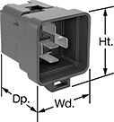 | 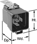 |  | 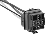 |
Relay-Socket Mount | Relay-Socket and Surface Mount | Sockets with Crimp- On Terminals | Sockets with Wire Leads |
Vehicle Relays | Sockets with Crimp- On Terminals | Sockets with Wire Leads | ||||||||||||||||||
|---|---|---|---|---|---|---|---|---|---|---|---|---|---|---|---|---|---|---|---|---|
Switching Current @ Voltage | ||||||||||||||||||||
No. of Terminals | Input Voltage, V DC | Off (Normally Open) Circuit Position | On (Normally Closed) Circuit Position | Max. Switching Voltage, V DC | Max. Starting Current, amp | Control Current, mA | Surge Suppression Coverage | Ht. | Wd. | Dp. | Quick-Disconnect Tab Wd. | Features | Each | Each | Each | |||||
Relay-Socket Mount | ||||||||||||||||||||
1 Circuit Controlled with 1 Off or 1 On—SPDT | ||||||||||||||||||||
| 5 | 12 | 40 amp @ 12V DC | 20 amp @ 12V DC | 18 | 150 | 114 | Partial | 1.4" | 1.4" | 1.8" | 0.11" | Extended Housing | 9672K302 | 000000 | ——— | 0 | 9672K304 | 000000 | ||
| 5 | 12 | 40 amp @ 12V DC | 20 amp @ 12V DC | 18 | 150 | 155 | Partial | 1.4" | 1.4" | 1.8" | 0.25" | Extended Housing | 9672K301 | 00000 | 8228K19 | 000000 | 8228K15 | 00000 | ||
Relay-Socket and Surface Mount | ||||||||||||||||||||
1 Circuit Controlled with 1 Off or 1 On—SPDT | ||||||||||||||||||||
| 5 | 12 | 40 amp @ 12V DC | 20 amp @ 12V DC | 18 | 150 | 114 | Partial | 1.4" | 1.4" | 1.8" | 0.11" | Extended Housing | 9672K303 | 00000 | ——— | 0 | 9672K304 | 00000 | ||
| 5 | 12 | 40 amp @ 12V DC | 20 amp @ 12V DC | 18 | 150 | 138 | Partial | 1.4" | 1.4" | 1.8" | 0.25" | Extended Housing | 9672K44 | 00000 | 8228K19 | 00000 | 8228K15 | 00000 | ||
| 5 | 24 | 20 amp @ 24V DC | 10 amp @ 24V DC | 40 | 120 | 107 | Partial | 1.4" | 1.4" | 1.8" | 0.25" | Extended Housing | 9672K35 | 00000 | 8228K19 | 00000 | 8228K44 | 00000 | ||
