Filter by
Switch Designation
Position Designation
Switch Action
Switching Current
Input Voltage
Actuator Style


Switch Starting Position
Illumination
Export Control Classification Number (ECCN)
Certification
DFARS Specialty Metals

About Electrical Switches
Choose a switch with the right trigger type, number of inputs, and control functions to power your equipment.
Toggle Switches
 |
Rounded Toggle |
Note: Illuminated switches include a bulb. If wiring the switch and the bulb to the same circuit, the circuit voltage must not exceed bulb voltage.
On-On—Switches with an on-on or on-(on) position designation alternate power between sets of terminals.
No. of Circuits Controlled | Switch Starting Position | Switch Action | No. of Terminals | Switch Designation | Position Designation | Switching Current @ Voltage | Max. Voltage | For Max. Panel Thk. | Mounting Hardware Included | Mounting Thread Size | Choose a Wire Connection | Each | |||
|---|---|---|---|---|---|---|---|---|---|---|---|---|---|---|---|
2 Position with Rounded Toggle | |||||||||||||||
For 1/2" Diameter Panel Cutouts | |||||||||||||||
| 4 | 4 Off or 4 On | Maintained | 12 | 4PDT | On-On | 15 amp @ 125V AC/28V DC | 28V DC 250V AC | 0.13" | Yes | 15/32"-32 | Screw Terminal, Tab | 7343K891 | 000000 | ||
3 Position with Rounded Toggle | |||||||||||||||
For 1/2" Diameter Panel Cutouts | |||||||||||||||
| 4 | 4 Off or 4 On | Maintained | 12 | 4PDT | On-Off-On | 15 amp @ 125V AC/28V DC | 28V DC 250V AC | 0.13" | Yes | 15/32"-32 | Screw Terminal, Tab | 7343K881 | 00000 | ||
Mil. Spec. Washdown Toggle Switches
 |
These switches meet MIL-S-3950. A rubber seal protects them from washdowns.
On-On—Switches with an on-on, on-on-on, or (on)-on-on position designation alternate power between sets of terminals.
No. of Circuits Controlled | Switch Starting Position | Switch Action | No. of Terminals | Switch Designation | Position Designation | Switching Current @ Voltage | Max. Voltage | Dp. Behind Panel | Mounting Hardware Included | Wire Connection | Each | |||
|---|---|---|---|---|---|---|---|---|---|---|---|---|---|---|
2 Positions | ||||||||||||||
For 1/2" Diameter Panel Cutouts | ||||||||||||||
| 4 | 4 Off or 4 On | Maintained | 12 | 4PDT | On-On | 15 amp @ 125V AC, 12 amp @ 28V DC | 28V DC 125V AC | 1.35" | Yes | Screw Terminal | 8002K135 | 000000 | ||
3 Positions | ||||||||||||||
For 1/2" Diameter Panel Cutouts | ||||||||||||||
| 4 | 4 Off or 4 On | Maintained | 12 | 4PDT | On-Off-On | 15 amp @ 125V AC, 12 amp @ 28V DC | 28V DC 125V AC | 1.35" | Yes | Screw Terminal | 8002K133 | 00000 | ||
| 4 | 4 Off or 4 On | Momentary | 12 | 4PDT | (On)-Off-(On) | 8 amp @ 125V AC, 10 amp @ 28V AC | 28V DC 125V AC | 1.35" | Yes | Screw Terminal | 8002K136 | 00000 | ||
High-Current Toggle Switches
 |
Able to withstand high currents, these switches are often used with motors and pumps.
On-On—Switches with an on-on position designation alternate power between sets of terminals.
No. of Circuits Controlled | Switch Starting Position | Switch Action | No. of Terminals | Switch Designation | Position Designation | Switching Current @ Voltage | Max. Voltage | Dp. Behind Panel | Mounting Hardware Included | Each | |||
|---|---|---|---|---|---|---|---|---|---|---|---|---|---|
2 Position with Quick-Disconnect Terminals | |||||||||||||
For 1/2" Diameter Panel Cutouts | |||||||||||||
| 4 | 4 Off or 4 On | Maintained | 12 | 4PDT | On-On | 20 amp @ 125V AC, 20 amp @ 30V DC | 30V DC 250V AC | 1.3" | Yes | 8001K26 | 000000 | ||
2 Position with Tab | |||||||||||||
For 1/2" Diameter Panel Cutouts | |||||||||||||
| 4 | 4 Off or 4 On | Maintained | 12 | 4PDT | On-On | 20 amp @ 125V AC, 20 amp @ 30V DC | 30V DC 250V AC | 1.07" | Yes | 8001K37 | 00000 | ||
3 Position with Quick-Disconnect Terminals | |||||||||||||
For 1/2" Diameter Panel Cutouts | |||||||||||||
| 4 | 4 Off or 4 On | Maintained | 12 | 4PDT | On-Off-On | 20 amp @ 125V AC, 20 amp @ 30V DC | 30V DC 250V AC | 1.3" | Yes | 8001K28 | 00000 | ||
3 Position with Tab | |||||||||||||
For 1/2" Diameter Panel Cutouts | |||||||||||||
| 4 | 4 Off or 4 On | Maintained | 12 | 4PDT | On-Off-On | 20 amp @ 125V AC, 20 amp @ 30V DC | 30V DC 250V AC | 1.07" | Yes | 8001K38 | 00000 | ||
Miniature Toggle Switches
 |
Maximize the space in a panel—these switches are half the size of most toggle switches.
On-On—Switches with an on-on or on-(on) position designation alternate power between sets of terminals.
No. of Circuits Controlled | Switch Starting Position | Switch Action | No. of Terminals | Switch Designation | Position Designation | Switching Current @ Voltage | Max. Voltage | For Max. Panel Thk. | Mounting Hardware Included | Mounting Thread Size | Wire Connection | Each | |||
|---|---|---|---|---|---|---|---|---|---|---|---|---|---|---|---|
2 Position with Rounded Toggle | |||||||||||||||
For 1/4" Diameter Panel Cutouts | |||||||||||||||
| 4 | 4 Off or 4 On | Maintained | 12 | 4PDT | On-On | 6 amp @ 125V AC, 4 amp @ 30V DC | 30V DC 250V AC | 0.16" | Yes | 1/4"-40 | Tab | 7347K99 | 000000 | ||
Wet-Environment Toggle Switches
 |
Rounded Toggle |
A rubber seal protects these switches from splashing water.
IP68 Enclosure Rating, NEMA 4 Enclosure Rating, and NEMA 13 Enclosure Rating—NEMA 4, 13, and IP68 rated switches are protected against oil/coolant spraying, washdowns, and temporary submersion.
On-On—Switches with an on-on or on-(on) position designation alternate power between sets of terminals.
No. of Circuits Controlled | Switch Starting Position | Switch Action | No. of Terminals | Switch Designation | Position Designation | Switching Current @ Voltage | Max. Voltage | For Max. Panel Thk. | Mounting Hardware Included | Mounting Thread Size | Wire Connection | Each | |||
|---|---|---|---|---|---|---|---|---|---|---|---|---|---|---|---|
2 Position with Rounded Toggle—NEMA 4, NEMA 13, IP68 | |||||||||||||||
For 1/2" Diameter Panel Cutouts | |||||||||||||||
| 4 | 4 Off or 4 On | Maintained | 12 | 4PDT | On-On | 15 amp @ 125V AC, 12 amp @ 28V DC | 28V DC 277V AC | 0.13" | Yes | 15/32"-32 | Quick-Disconnect Terminal | 8002K381 | 000000 | ||
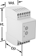
Smart Multifunction Monitoring Relays
 |
Remotely control these relays through an app on your smartphone—they simultaneously monitor phase, voltage, and frequency. The downloadable app lets you change the tripping range, modify settings, and save programs to apply to multiple relays. Tap your smartphone or tablet to the relays to connect to them. They use NFC (near field communication), so you don’t need to manually pair them like Bluetooth devices.
You’ll often see these relays used to protect motors, generators, and other three-phase circuits from burning out or overheating. They'll switch the circuit off if they detect voltage or frequencies outside of the set range or phase loss, imbalance, or reversal. You can see that they're wired correctly and when they're actuated based on the LED indicators. Rated IP20, they have recessed terminals that keep fingers and other objects from touching live circuits. Mount them on a 35 mm DIN rail (also known as DIN 3 rail) for fast installation.
No. of Terminals | Input Voltage, V AC | Trip Voltage, V AC | Input Freq., Hz | Trip Freq., Hz | Trip Time, sec. | Reset Type | Switching Current @ Voltage | Max. Switching Voltage, V AC | Ht. | Wd. | Dp. | Operating System Compatibility | Each | |||
|---|---|---|---|---|---|---|---|---|---|---|---|---|---|---|---|---|
2 Circuits Controlled with 2 Off or 2 On—DPDT | ||||||||||||||||
With Screw Terminals | ||||||||||||||||
| 12 | 208, 240, 300, 480 | 208 to 480 | 50, 60 | 45 to 66 | 0.1 to 60 | Automatic | 8 amp @ 240V AC | 250 | 3.5" | 0.9" | 3.9" | Android 7.0 or Later, iOS 14.5 or Later | 8452N11 | 0000000 | ||
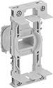
Frame-Mounted Safety Switches
 |
Key Shown Actuating from the Side |
 |
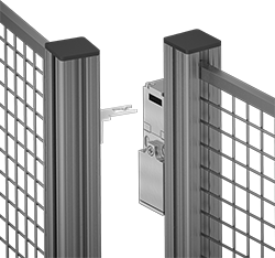
Style J |
Also known as interlock switches, these ensure the safety of personnel by automatically shutting off power to machinery when an access door opens. Mount the switch to the door frame and mount a key to the door so that the key is inserted into the switch when the door is closed. When the door opens, the key is removed from the switch and the machine shuts down. They’re often used with machine guards for large robots.
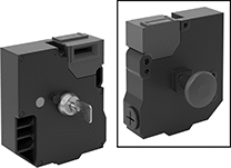
Style J—Style J switches have extra safety controls to prevent you from getting trapped next to running machinery. They actuate with the turn of a portable key. Bring the key when you enter an enclosure to ensure machinery won’t start while you’re inside, even if the door closes behind you. As an added fail-safe, a rear release button lets you cut power from inside of enclosures if needed. These switches have light-up indicators that show when they're properly installed and whether they're actuated.
IP67 Enclosure Rating—IP67 rated switches protect against temporary submersion.
Key Included—All switches require an actuator key, but not all include one—check whether you need to pick out a separate actuator key. For some switch styles, you can also select the mounting orientation of the key.
Housing | Conduit | |||||||||||||||||
|---|---|---|---|---|---|---|---|---|---|---|---|---|---|---|---|---|---|---|
Style | No. of Circuits Controlled | Switch Starting Position | Switch Action | No. of Terminals | Switch Designation | Switching Current @ Voltage | Max. Voltage | Ht. | Wd. | Dp. | Thread Size | Thread Type | Key Included | Enclosure Rating | Each | |||
Screw-Terminal Wire Connection with Rear Release Button, Portable Key, and LED Status Indicator | ||||||||||||||||||
| J | 6 | 2 Off and 4 On | Maintained | 12 | 6PST-2NO/4NC | 3 amp @ 240V AC, 2.5 amp @ 250V DC | 240V AC 250V DC | 5.2" | 4.6" | 2.2" | M20 | Metric | Yes | IP67 | 65665K101 | 0000000 | ||

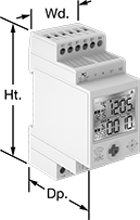
Programmable Potentiometers
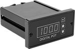 |
For quick, repeatable adjustments to electronic equipment, these potentiometers adjust and save electrical settings. They’re typically used to control speed, volume, or light intensity. For example, if a conveyor needs different speeds for different tasks, you can program each speed into them. Set the digital display to show the specific measurement unit for your application, such as motor rpm.
Install them in a standard 1/8 DIN panel cutout. They’re NEMA 4X rated to resist corrosion, washdowns, and weather.
For Panel Cutout | |||||||||||||||||
|---|---|---|---|---|---|---|---|---|---|---|---|---|---|---|---|---|---|
Input Voltage, V AC | Output Voltage, V DC | Input Freq., Hz | Digital Display Type | No. of Digits | Resolution | DIN Size | Ht. | Wd. | Dp. Behind Panel | Housing Material | Wire Connection | No. of Terminals | Mounting Fasteners Included | Enclosure Rating | Each | ||
| 85 to 250 | 0 to 24 | 50, 60 | LED | 4 | 0.1% | 1/8 | 1 3/4" | 3 5/8" | 4 5/8" | Aluminum | Screw Terminal | 12 | Yes | NEMA 4X | 8890N11 | 0000000 | |
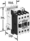
DIN-Rail Mount Touch-Safe Screw Terminal Relays
 |
Quickly and safely mount these relays on 35 mm DIN rail (also known as DIN 3). IP20 rated, they have recessed terminals that prevent fingers and other objects from touching live circuits.
3 Circuits Controlled and 4 Circuits Controlled—Relays that control 3 and 4 circuits are built to IEC dimensional standards and are often called IEC contactors.
12 Terminals—Relays with 12 terminals let you attach the control circuit onto the side that works best for your setup, which reduces the amount of wire you need.
hp @ Switching Voltage | |||||||||||||
|---|---|---|---|---|---|---|---|---|---|---|---|---|---|
No. of Terminals | Input Voltage | Control Power | Switching Current @ Voltage (Load Type) | Max. Switching Voltage, V AC | Single Phase | Three Phase | Ht. | Wd. | Dp. | Each | |||
3 Circuits Controlled with 3 Off—3PST-NO | |||||||||||||
With 1 Auxiliary Contact—1 Off | |||||||||||||
| 12 | 24V AC | 6.5 VA | 11 amp @ 600V AC (Full) 28 amp @ 600V AC (Resistive) | 600 | 1 hp @ 120V AC 2 hp @ 240V AC | 5 hp @ 240V AC 7 1/2 hp @ 480V AC 10 hp @ 600V AC | 3.2" | 1.8" | 3.2" | 70255K321 | 000000 | ||
| 12 | 24V AC | 6.5 VA | 17 amp @ 600V AC (Full) 32 amp @ 600V AC (Resistive) | 600 | 1 hp @ 120V AC 3 hp @ 240V AC | 5 hp @ 240V AC 10 hp @ 480V AC 15 hp @ 600V AC | 3.2" | 1.8" | 3.2" | 70255K331 | 00000 | ||
| 12 | 24V AC | 6.5 VA | 17 amp @ 600V AC (Full) 32 amp @ 600V AC (Resistive) | 600 | 2 hp @ 120V AC 3 hp @ 240V AC | 7 1/2 hp @ 240V AC 15 hp @ 480V AC 15 hp @ 600V AC | 3.2" | 1.8" | 3.2" | 70255K341 | 000000 | ||
| 12 | 120V AC | 6.5 VA | 11 amp @ 600V AC (Full) 28 amp @ 600V AC (Resistive) | 600 | 1 hp @ 120V AC 2 hp @ 240V AC | 5 hp @ 240V AC 7 1/2 hp @ 480V AC 10 hp @ 600V AC | 3.2" | 1.8" | 3.2" | 70255K322 | 00000 | ||
| 12 | 120V AC | 6.5 VA | 17 amp @ 600V AC (Full) 32 amp @ 600V AC (Resistive) | 600 | 1 hp @ 120V AC 3 hp @ 240V AC | 5 hp @ 240V AC 10 hp @ 480V AC 15 hp @ 600V AC | 3.2" | 1.8" | 3.2" | 70255K332 | 00000 | ||
| 12 | 120V AC | 6.5 VA | 17 amp @ 600V AC (Full) 32 amp @ 600V AC (Resistive) | 600 | 2 hp @ 120V AC 3 hp @ 240V AC | 7 1/2 hp @ 240V AC 15 hp @ 480V AC 15 hp @ 600V AC | 3.2" | 1.8" | 3.2" | 70255K342 | 000000 | ||
| 12 | 240V AC | 6.5 VA | 11 amp @ 600V AC (Full) 28 amp @ 600V AC (Resistive) | 600 | 1 hp @ 120V AC 2 hp @ 240V AC | 5 hp @ 240V AC 7 1/2 hp @ 480V AC 10 hp @ 600V AC | 3.2" | 1.8" | 3.2" | 70255K323 | 00000 | ||
| 12 | 240V AC | 6.5 VA | 17 amp @ 600V AC (Full) 32 amp @ 600V AC (Resistive) | 600 | 1 hp @ 120V AC 3 hp @ 240V AC | 5 hp @ 240V AC 10 hp @ 480V AC 15 hp @ 600V AC | 3.2" | 1.8" | 3.2" | 70255K333 | 00000 | ||
| 12 | 240V AC | 6.5 VA | 17 amp @ 600V AC (Full) 32 amp @ 600V AC (Resistive) | 600 | 2 hp @ 120V AC 3 hp @ 240V AC | 7 1/2 hp @ 240V AC 15 hp @ 480V AC 15 hp @ 600V AC | 3.2" | 1.8" | 3.2" | 70255K343 | 000000 | ||
| 12 | 24V DC | 5.4 W | 11 amp @ 600V AC (Full) 28 amp @ 600V AC (Resistive) | 600 | 1 hp @ 120V AC 2 hp @ 240V AC | 5 hp @ 240V AC 7 1/2 hp @ 480V AC 10 hp @ 600V AC | 3.2" | 1.8" | 3.9" | 70255K42 | 000000 | ||
| 12 | 24V DC | 5.4 W | 17 amp @ 600V AC (Full) 32 amp @ 600V AC (Resistive) | 600 | 1 hp @ 120V AC 3 hp @ 240V AC | 5 hp @ 240V AC 10 hp @ 480V AC 15 hp @ 600V AC | 3.2" | 1.8" | 3.9" | 70255K43 | 000000 | ||
| 12 | 24V DC | 5.4 W | 17 amp @ 600V AC (Full) 32 amp @ 600V AC (Resistive) | 600 | 2 hp @ 120V AC 3 hp @ 240V AC | 7 1/2 hp @ 240V AC 15 hp @ 480V AC 15 hp @ 600V AC | 3.2" | 1.8" | 3.9" | 70255K44 | 000000 | ||
With 1 Auxiliary Contact—1 On | |||||||||||||
| 12 | 24V AC | 6.5 VA | 11 amp @ 600V AC (Full) 28 amp @ 600V AC (Resistive) | 600 | 1 hp @ 120V AC 2 hp @ 240V AC | 5 hp @ 240V AC 7 1/2 hp @ 480V AC 10 hp @ 600V AC | 3.2" | 1.8" | 3.2" | 70255K351 | 00000 | ||
| 12 | 24V AC | 6.5 VA | 17 amp @ 600V AC (Full) 32 amp @ 600V AC (Resistive) | 600 | 1 hp @ 120V AC 3 hp @ 240V AC | 5 hp @ 240V AC 10 hp @ 480V AC 15 hp @ 600V AC | 3.2" | 1.8" | 3.2" | 70255K361 | 00000 | ||
| 12 | 24V AC | 6.5 VA | 17 amp @ 600V AC (Full) 32 amp @ 600V AC (Resistive) | 600 | 2 hp @ 120V AC 3 hp @ 240V AC | 7 1/2 hp @ 240V AC 15 hp @ 480V AC 15 hp @ 600V AC | 3.2" | 1.8" | 3.2" | 70255K371 | 000000 | ||
| 12 | 120V AC | 6.5 VA | 11 amp @ 600V AC (Full) 28 amp @ 600V AC (Resistive) | 600 | 1 hp @ 120V AC 2 hp @ 240V AC | 5 hp @ 240V AC 7 1/2 hp @ 480V AC 10 hp @ 600V AC | 3.2" | 1.8" | 3.2" | 70255K352 | 00000 | ||
| 12 | 120V AC | 6.5 VA | 17 amp @ 600V AC (Full) 32 amp @ 600V AC (Resistive) | 600 | 1 hp @ 120V AC 3 hp @ 240V AC | 5 hp @ 240V AC 10 hp @ 480V AC 15 hp @ 600V AC | 3.2" | 1.8" | 3.2" | 70255K362 | 00000 | ||
| 12 | 120V AC | 6.5 VA | 17 amp @ 600V AC (Full) 32 amp @ 600V AC (Resistive) | 600 | 2 hp @ 120V AC 3 hp @ 240V AC | 7 1/2 hp @ 240V AC 15 hp @ 480V AC 15 hp @ 600V AC | 3.2" | 1.8" | 3.2" | 70255K372 | 000000 | ||
| 12 | 240V AC | 6.5 VA | 11 amp @ 600V AC (Full) 28 amp @ 600V AC (Resistive) | 600 | 1 hp @ 120V AC 2 hp @ 240V AC | 5 hp @ 240V AC 7 1/2 hp @ 480V AC 10 hp @ 600V AC | 3.2" | 1.8" | 3.2" | 70255K353 | 00000 | ||
| 12 | 240V AC | 6.5 VA | 17 amp @ 600V AC (Full) 32 amp @ 600V AC (Resistive) | 600 | 1 hp @ 120V AC 3 hp @ 240V AC | 5 hp @ 240V AC 10 hp @ 480V AC 15 hp @ 600V AC | 3.2" | 1.8" | 3.2" | 70255K363 | 00000 | ||
| 12 | 240V AC | 6.5 VA | 17 amp @ 600V AC (Full) 32 amp @ 600V AC (Resistive) | 600 | 2 hp @ 120V AC 3 hp @ 240V AC | 7 1/2 hp @ 240V AC 15 hp @ 480V AC 15 hp @ 600V AC | 3.2" | 1.8" | 3.2" | 70255K373 | 000000 | ||
| 12 | 24V DC | 5.4 W | 11 amp @ 600V AC (Full) 28 amp @ 600V AC (Resistive) | 600 | 1 hp @ 120V AC 2 hp @ 240V AC | 5 hp @ 240V AC 7 1/2 hp @ 480V AC 10 hp @ 600V AC | 3.2" | 1.8" | 3.9" | 70255K45 | 000000 | ||
| 12 | 24V DC | 5.4 W | 17 amp @ 600V AC (Full) 32 amp @ 600V AC (Resistive) | 600 | 1 hp @ 120V AC 3 hp @ 240V AC | 5 hp @ 240V AC 10 hp @ 480V AC 15 hp @ 600V AC | 3.2" | 1.8" | 3.9" | 70255K46 | 000000 | ||
| 12 | 24V DC | 5.4 W | 17 amp @ 600V AC (Full) 32 amp @ 600V AC (Resistive) | 600 | 2 hp @ 120V AC 3 hp @ 240V AC | 7 1/2 hp @ 240V AC 15 hp @ 480V AC 15 hp @ 600V AC | 3.2" | 1.8" | 3.9" | 70255K47 | 000000 | ||
4 Circuits Controlled with 4 Off—4PST-NO | |||||||||||||
| 12 | 24V AC | 6.5 VA | 9 amp @ 600V AC (Full) 25 amp @ 600V AC (Resistive) | 600 | 3/4 hp @ 120V AC 2 hp @ 240V AC | 3 hp @ 240V AC 5 hp @ 480V AC 7 1/2 hp @ 600V AC | 3.2" | 1.8" | 3.2" | 70255K651 | 00000 | ||
| 12 | 24V AC | 6.5 VA | 11 amp @ 600V AC (Full) 28 amp @ 600V AC (Resistive) | 600 | 1 hp @ 120V AC 2 hp @ 240V AC | 5 hp @ 240V AC 7 1/2 hp @ 480V AC 10 hp @ 600V AC | 3.2" | 1.8" | 3.2" | 70255K391 | 000000 | ||
| 12 | 24V AC | 6.5 VA | 17 amp @ 600V AC (Full) 32 amp @ 600V AC (Resistive) | 600 | 1 hp @ 120V AC 3 hp @ 240V AC | 5 hp @ 240V AC 10 hp @ 480V AC 15 hp @ 600V AC | 3.2" | 1.8" | 3.2" | 70255K551 | 000000 | ||
| 12 | 24V AC | 6.5 VA | 22 amp @ 600V AC (Full) 45 amp @ 600V AC (Resistive) | 600 | 2 hp @ 120V AC 5 hp @ 240V AC | 7 1/2 hp @ 240V AC 15 hp @ 480V AC 20 hp @ 600V AC | 3.5" | 2.4" | 3.5" | 70255K411 | 000000 | ||
| 12 | 24V AC | 6.5 VA | 32 amp @ 600V AC (Full) 55 amp @ 600V AC (Resistive) | 600 | 3 hp @ 120V AC 7 1/2 hp @ 240V AC | 15 hp @ 240V AC 30 hp @ 480V AC 30 hp @ 600V AC | 3.5" | 2.4" | 3.5" | 70255K271 | 000000 | ||
| 12 | 120V AC | 6.5 VA | 9 amp @ 600V AC (Full) 25 amp @ 600V AC (Resistive) | 600 | 3/4 hp @ 120V AC 2 hp @ 240V AC | 3 hp @ 240V AC 5 hp @ 480V AC 7 1/2 hp @ 600V AC | 3.2" | 1.8" | 3.2" | 70255K652 | 00000 | ||
| 12 | 120V AC | 6.5 VA | 11 amp @ 600V AC (Full) 28 amp @ 600V AC (Resistive) | 600 | 1 hp @ 120V AC 2 hp @ 240V AC | 5 hp @ 240V AC 7 1/2 hp @ 480V AC 10 hp @ 600V AC | 3.2" | 1.8" | 3.2" | 70255K392 | 000000 | ||
| 12 | 120V AC | 6.5 VA | 17 amp @ 600V AC (Full) 32 amp @ 600V AC (Resistive) | 600 | 1 hp @ 120V AC 3 hp @ 240V AC | 5 hp @ 240V AC 10 hp @ 480V AC 15 hp @ 600V AC | 3.2" | 1.8" | 3.2" | 70255K552 | 000000 | ||
| 12 | 120V AC | 6.5 VA | 22 amp @ 600V AC (Full) 45 amp @ 600V AC (Resistive) | 600 | 2 hp @ 120V AC 5 hp @ 240V AC | 7 1/2 hp @ 240V AC 15 hp @ 480V AC 20 hp @ 600V AC | 3.5" | 2.4" | 3.5" | 70255K412 | 000000 | ||
| 12 | 120V AC | 6.5 VA | 32 amp @ 600V AC (Full) 55 amp @ 600V AC (Resistive) | 600 | 3 hp @ 120V AC 7 1/2 hp @ 240V AC | 15 hp @ 240V AC 30 hp @ 480V AC 30 hp @ 600V AC | 3.5" | 2.4" | 3.5" | 70255K272 | 000000 | ||
| 12 | 240V AC | 6.5 VA | 9 amp @ 600V AC (Full) 25 amp @ 600V AC (Resistive) | 600 | 3/4 hp @ 120V AC 2 hp @ 240V AC | 3 hp @ 240V AC 5 hp @ 480V AC 7 1/2 hp @ 600V AC | 3.2" | 1.8" | 3.2" | 70255K653 | 00000 | ||
| 12 | 240V AC | 6.5 VA | 11 amp @ 600V AC (Full) 28 amp @ 600V AC (Resistive) | 600 | 1 hp @ 120V AC 2 hp @ 240V AC | 5 hp @ 240V AC 7 1/2 hp @ 480V AC 10 hp @ 600V AC | 3.2" | 1.8" | 3.2" | 70255K393 | 000000 | ||
| 12 | 240V AC | 6.5 VA | 17 amp @ 600V AC (Full) 32 amp @ 600V AC (Resistive) | 600 | 1 hp @ 120V AC 3 hp @ 240V AC | 5 hp @ 240V AC 10 hp @ 480V AC 15 hp @ 600V AC | 3.2" | 1.8" | 3.2" | 70255K553 | 000000 | ||
| 12 | 240V AC | 6.5 VA | 22 amp @ 600V AC (Full) 45 amp @ 600V AC (Resistive) | 600 | 2 hp @ 120V AC 5 hp @ 240V AC | 7 1/2 hp @ 240V AC 15 hp @ 480V AC 20 hp @ 600V AC | 3.5" | 2.4" | 3.5" | 70255K413 | 000000 | ||
| 12 | 240V AC | 6.5 VA | 32 amp @ 600V AC (Full) 55 amp @ 600V AC (Resistive) | 600 | 3 hp @ 120V AC 7 1/2 hp @ 240V AC | 15 hp @ 240V AC 30 hp @ 480V AC 30 hp @ 600V AC | 3.5" | 2.4" | 3.5" | 70255K273 | 000000 | ||
| 12 | 24V DC | 5.4 W | 9 amp @ 600V AC (Full) 25 amp @ 600V AC (Resistive) | 600 | 3/4 hp @ 120V AC 2 hp @ 240V AC | 3 hp @ 240V AC 5 hp @ 480V AC 7 1/2 hp @ 600V AC | 3.2" | 1.8" | 3.9" | 70255K28 | 000000 | ||
| 12 | 24V DC | 5.4 W | 17 amp @ 600V AC (Full) 32 amp @ 600V AC (Resistive) | 600 | 1 hp @ 120V AC 3 hp @ 240V AC | 5 hp @ 240V AC 10 hp @ 480V AC 15 hp @ 600V AC | 3.2" | 1.8" | 3.9" | 70255K49 | 000000 | ||
| 12 | 24V DC | 5.4 W | 22 amp @ 600V AC (Full) 45 amp @ 600V AC (Resistive) | 600 | 2 hp @ 120V AC 5 hp @ 240V AC | 7 1/2 hp @ 240V AC 15 hp @ 480V AC 20 hp @ 600V AC | 3.5" | 2.4" | 4.2" | 70255K66 | 000000 | ||
| 12 | 24V DC | 5.4 W | 32 amp @ 600V AC (Full) 55 amp @ 600V AC (Resistive) | 600 | 3 hp @ 120V AC 7 1/2 hp @ 240V AC | 15 hp @ 240V AC 30 hp @ 480V AC 30 hp @ 600V AC | 3.5" | 2.4" | 4.2" | 70255K38 | 000000 | ||
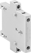
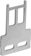
 |
Front Mount |
No. of Circuits Controlled | For Relay Wd. | Switch Starting Position | Switch Designation | Mounting Location | Each | ||
|---|---|---|---|---|---|---|---|
| 2 | 1.8", 2.2", 2.4" | 2 Off | DPST-NO | Front | 8728N12 | 000000 | |
| 2 | 1.8", 2.2", 2.4" | 2 On | DPST-NC | Front | 8728N11 | 00000 | |
| 4 | 1.8", 2.2", 2.4" | 1 Off and 3 On | 4PST-1NO/3NC | Front | 8728N15 | 00000 | |
| 4 | 1.8", 2.2", 2.4" | 2 Off and 2 On | 4PST-2NO/2NC | Front | 8728N16 | 00000 | |
| 4 | 1.8", 2.2", 2.4" | 3 Off and 1 On | 4PST-3NO/1NC | Front | 8728N17 | 00000 | |
| 4 | 1.8", 2.2", 2.4" | 4 Off | 4PST-NO | Front | 8728N14 | 00000 | |
| 4 | 1.8", 2.2", 2.4" | 4 On | 4PST-NC | Front | 8728N13 | 00000 |
 |
For Switching Current (Load Type) | Input Voltage, V AC | Input Freq., Hz | Each | ||
|---|---|---|---|---|---|
| 9 amp to 17 amp (Full) | 24 | 60 | 8727N11 | 000000 | |
| 9 amp to 17 amp (Full) | 120 | 60 | 8727N12 | 00000 | |
| 9 amp to 17 amp (Full) | 240 | 60 | 8727N13 | 00000 | |
| 22 amp to 32 amp (Full) | 24 | 60 | 8727N14 | 00000 | |
| 22 amp to 32 amp (Full) | 120 | 60 | 8727N15 | 00000 | |
| 22 amp to 32 amp (Full) | 240 | 60 | 8727N16 | 00000 |
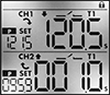
Dual-Channel DIN-Rail Mount Multifunction Timer Relays
 |  |
Timing Range | |||||||||||||||
|---|---|---|---|---|---|---|---|---|---|---|---|---|---|---|---|
No. of Terminals | Input Voltage | Control Current, mA | Timer Relay Function | No. of | Overall | Switching Current @ Voltage | Max. Switching Voltage, V AC | Ht. | Wd. | Dp. | Features | Each | |||
2 Circuits Controlled with 2 Off and 2 On—DPDT | |||||||||||||||
| 12 | 12V AC, 24V AC, 12V DC, 24V DC | 8 | Manual Switch Control Fixed On/Off Switch on (Single Shot) Delayed Start (Delay on Make) Delayed Switch Off (Delay on Break) Delayed Switch-On with Delayed Switch-Off Interval Repeat Cycle Asymmetrical Repeat Cycle Switch-On Asymmetrical Repeat Cycle | 30 | 0.1 sec. to 9,999 hr. | 16 amp @ 240V AC | 240 | 3.4" | 1.4" | 2.2" | 2 Individually Programmable Timers, LCD Screen, Proximity Sensor Compatability (PNP and NPN) | 7105N11 | 0000000 | ||
| 12 | 120V AC, 240V AC, 110V DC, 240V DC | 16 | Manual Switch Control Fixed On/Off Switch on (Single Shot) Delayed Start (Delay on Make) Delayed Switch Off (Delay on Break) Delayed Switch-On with Delayed Switch-Off Interval Repeat Cycle Asymmetrical Repeat Cycle Switch-On Asymmetrical Repeat Cycle | 30 | 0.1 sec. to 9,999 hr. | 16 amp @ 240V AC | 240 | 3.4" | 1.4" | 2.2" | 2 Individually Programmable Timers, LCD Screen | 7105N12 | 000000 | ||
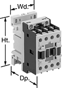
Touch-Safe DIN-Rail Mount Infrequent-Cycle Relays
 |
12 Terminals |
Operate equipment that cycles on and off from your control cabinet. Often called definite-purpose contactors, these relays meet UL 508 for use with air conditioning and heating. Mount them directly to 35 mm DIN rail (also known as DIN 3 rail) for fast installation. They have recessed terminals that prevent fingers and other objects from touching live circuits. You can wire the control circuit on either side of the relay, which helps you use less wire.
Switching Current @ 600V AC, amp | hp @ Switching Voltage | |||||||||||||
|---|---|---|---|---|---|---|---|---|---|---|---|---|---|---|
No. of Terminals | Input Voltage | Control Power | Full Load | Resistive Load | Max. Switching Voltage, V AC | Single Phase | Three Phase | Ht. | Wd. | Dp. | Each | |||
Infrequent-Cycle Relays | ||||||||||||||
4 Circuits Controlled with 4 Off—4PST-NO | ||||||||||||||
| 12 | 24V AC | 9 VA | 20 | 30 | 600 | 1 1/2 hp @ 120V AC 3 hp @ 240V AC | 5 hp @ 240V AC 10 hp @ 480V AC 15 hp @ 600V AC | 3.2" | 1.8" | 3.2" | 9114T371 | 000000 | ||
| 12 | 24V AC | 9 VA | 25 | 30 | 600 | 2 hp @ 120V AC 3 hp @ 240V AC | 5 hp @ 240V AC 10 hp @ 480V AC 15 hp @ 600V AC | 3.2" | 1.8" | 3.2" | 9114T381 | 00000 | ||
| 12 | 24V AC | 9 VA | 30 | 32 | 600 | 2 hp @ 120V AC 5 hp @ 240V AC | 7 1/2 hp @ 240V AC 15 hp @ 480V AC 20 hp @ 600V AC | 3.2" | 1.8" | 3.2" | 9114T391 | 00000 | ||
| 12 | 24V AC | 9 VA | 40 | 50 | 600 | 3 hp @ 120V AC 7 1/2 hp @ 240V AC | 10 hp @ 240V AC 30 hp @ 480V AC 40 hp @ 600V AC | 3.5" | 2.4" | 3.5" | 9114T411 | 000000 | ||
| 12 | 120V AC | 9 VA | 20 | 30 | 600 | 1 1/2 hp @ 120V AC 3 hp @ 240V AC | 5 hp @ 240V AC 10 hp @ 480V AC 15 hp @ 600V AC | 3.2" | 1.8" | 3.2" | 9114T372 | 00000 | ||
| 12 | 120V AC | 9 VA | 25 | 30 | 600 | 2 hp @ 120V AC 3 hp @ 240V AC | 5 hp @ 240V AC 10 hp @ 480V AC 15 hp @ 600V AC | 3.2" | 1.8" | 3.2" | 9114T382 | 00000 | ||
| 12 | 120V AC | 9 VA | 30 | 32 | 600 | 2 hp @ 120V AC 5 hp @ 240V AC | 7 1/2 hp @ 240V AC 15 hp @ 480V AC 20 hp @ 600V AC | 3.2" | 1.8" | 3.2" | 9114T392 | 00000 | ||
| 12 | 120V AC | 9 VA | 40 | 50 | 600 | 3 hp @ 120V AC 7 1/2 hp @ 240V AC | 10 hp @ 240V AC 30 hp @ 480V AC 40 hp @ 600V AC | 3.5" | 2.4" | 3.5" | 9114T412 | 000000 | ||
| 12 | 240V AC | 9 VA | 20 | 30 | 600 | 1 1/2 hp @ 120V AC 3 hp @ 240V AC | 5 hp @ 240V AC 10 hp @ 480V AC 15 hp @ 600V AC | 3.2" | 1.8" | 3.2" | 9114T373 | 00000 | ||
| 12 | 240V AC | 9 VA | 25 | 30 | 600 | 2 hp @ 120V AC 3 hp @ 240V AC | 5 hp @ 240V AC 10 hp @ 480V AC 15 hp @ 600V AC | 3.2" | 1.8" | 3.2" | 9114T383 | 00000 | ||
| 12 | 240V AC | 9 VA | 30 | 32 | 600 | 2 hp @ 120V AC 5 hp @ 240V AC | 7 1/2 hp @ 240V AC 15 hp @ 480V AC 20 hp @ 600V AC | 3.2" | 1.8" | 3.2" | 9114T393 | 00000 | ||
| 12 | 240V AC | 9 VA | 40 | 50 | 600 | 3 hp @ 120V AC 7 1/2 hp @ 240V AC | 10 hp @ 240V AC 30 hp @ 480V AC 40 hp @ 600V AC | 3.5" | 2.4" | 3.5" | 9114T413 | 000000 | ||
| 12 | 24V DC | 5.4 W | 20 | 30 | 600 | 1 1/2 hp @ 120V AC 3 hp @ 240V AC | 5 hp @ 240V AC 10 hp @ 480V AC 15 hp @ 600V AC | 3.2" | 1.8" | 3.9" | 9114T53 | 000000 | ||
Infrequent-Cycle Relays with 1 Off Auxiliary Contact Switch | ||||||||||||||
3 Circuits Controlled with 3 Off—3PST-NO | ||||||||||||||
| 12 | 24V AC | 9 VA | 20 | 30 | 600 | 1 1/2 hp @ 120V AC 3 hp @ 240V AC | 5 hp @ 240V AC 10 hp @ 480V AC 15 hp @ 600V AC | 3.2" | 1.8" | 3.2" | 9114T321 | 00000 | ||
| 12 | 24V AC | 9 VA | 25 | 30 | 600 | 2 hp @ 120V AC 3 hp @ 240V AC | 5 hp @ 240V AC 10 hp @ 480V AC 15 hp @ 600V AC | 3.2" | 1.8" | 3.2" | 9114T331 | 00000 | ||
| 12 | 24V AC | 9 VA | 30 | 32 | 600 | 2 hp @ 120V AC 5 hp @ 240V AC | 7 1/2 hp @ 240V AC 15 hp @ 480V AC 20 hp @ 600V AC | 3.2" | 1.8" | 3.2" | 9114T341 | 00000 | ||
| 12 | 120V AC | 9 VA | 20 | 30 | 600 | 1 1/2 hp @ 120V AC 3 hp @ 240V AC | 5 hp @ 240V AC 10 hp @ 480V AC 15 hp @ 600V AC | 3.2" | 1.8" | 3.2" | 9114T322 | 00000 | ||
| 12 | 120V AC | 9 VA | 25 | 30 | 600 | 2 hp @ 120V AC 3 hp @ 240V AC | 5 hp @ 240V AC 10 hp @ 480V AC 15 hp @ 600V AC | 3.2" | 1.8" | 3.2" | 9114T332 | 00000 | ||
| 12 | 120V AC | 9 VA | 30 | 32 | 600 | 2 hp @ 120V AC 5 hp @ 240V AC | 7 1/2 hp @ 240V AC 15 hp @ 480V AC 20 hp @ 600V AC | 3.2" | 1.8" | 3.2" | 9114T342 | 00000 | ||
| 12 | 240V AC | 9 VA | 20 | 30 | 600 | 1 1/2 hp @ 120V AC 3 hp @ 240V AC | 5 hp @ 240V AC 10 hp @ 480V AC 15 hp @ 600V AC | 3.2" | 1.8" | 3.2" | 9114T323 | 00000 | ||
| 12 | 240V AC | 9 VA | 25 | 30 | 600 | 2 hp @ 120V AC 3 hp @ 240V AC | 5 hp @ 240V AC 10 hp @ 480V AC 15 hp @ 600V AC | 3.2" | 1.8" | 3.2" | 9114T333 | 00000 | ||
| 12 | 240V AC | 9 VA | 30 | 32 | 600 | 2 hp @ 120V AC 5 hp @ 240V AC | 7 1/2 hp @ 240V AC 15 hp @ 480V AC 20 hp @ 600V AC | 3.2" | 1.8" | 3.2" | 9114T343 | 00000 | ||
| 12 | 24V DC | 5.4 W | 20 | 30 | 600 | 1 1/2 hp @ 120V AC 3 hp @ 240V AC | 5 hp @ 240V AC 10 hp @ 480V AC 15 hp @ 600V AC | 3.2" | 1.8" | 3.9" | 9114T42 | 000000 | ||
| 12 | 24V DC | 5.4 W | 25 | 30 | 600 | 2 hp @ 120V AC 3 hp @ 240V AC | 5 hp @ 240V AC 10 hp @ 480V AC 15 hp @ 600V AC | 3.2" | 1.8" | 3.9" | 9114T43 | 000000 | ||
| 12 | 24V DC | 5.4 W | 30 | 32 | 600 | 2 hp @ 120V AC 5 hp @ 240V AC | 7 1/2 hp @ 240V AC 15 hp @ 480V AC 20 hp @ 600V AC | 3.2" | 1.8" | 3.9" | 9114T44 | 000000 | ||
|
Front Mount |
No. of Circuits Controlled | For Relay Wd. | Switch Starting Position | Switch Designation | Mounting Location | Each | ||
|---|---|---|---|---|---|---|---|
| 2 | 1.8", 2.2", 2.4" | 2 Off | DPST-NO | Front | 8728N12 | 000000 | |
| 2 | 1.8", 2.2", 2.4" | 2 On | DPST-NC | Front | 8728N11 | 00000 | |
| 4 | 1.8", 2.2", 2.4" | 1 Off and 3 On | 4PST-1NO/3NC | Front | 8728N15 | 00000 | |
| 4 | 1.8", 2.2", 2.4" | 2 Off and 2 On | 4PST-2NO/2NC | Front | 8728N16 | 00000 | |
| 4 | 1.8", 2.2", 2.4" | 3 Off and 1 On | 4PST-3NO/1NC | Front | 8728N17 | 00000 | |
| 4 | 1.8", 2.2", 2.4" | 4 Off | 4PST-NO | Front | 8728N14 | 00000 | |
| 4 | 1.8", 2.2", 2.4" | 4 On | 4PST-NC | Front | 8728N13 | 00000 |
|
For Switching Current (Load Type) | Input Voltage, V AC | Input Freq., Hz | Each | ||
|---|---|---|---|---|---|
| 9 amp to 17 amp (Full) | 24 | 60 | 8727N11 | 000000 | |
| 9 amp to 17 amp (Full) | 120 | 60 | 8727N12 | 00000 | |
| 9 amp to 17 amp (Full) | 240 | 60 | 8727N13 | 00000 | |
| 22 amp to 32 amp (Full) | 24 | 60 | 8727N14 | 00000 | |
| 22 amp to 32 amp (Full) | 120 | 60 | 8727N15 | 00000 | |
| 22 amp to 32 amp (Full) | 240 | 60 | 8727N16 | 00000 |
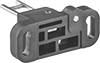
Corrosion-Resistant Washdown Foot Switches
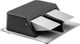 | 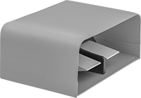 |
Style D | Style F |
1 Speed with Quick-Disconnect Terminals
| |
Style D | Style F |
Foot Switches | Foot Switch Pedals | ||||||||||||||||
|---|---|---|---|---|---|---|---|---|---|---|---|---|---|---|---|---|---|
Mounting | |||||||||||||||||
Style | No. of Circuits Controlled | Switch Starting Position | Switch Action | Switch Designation | Switching Current @ Voltage | No. of Terminals | Quick-Disconnect Tab Wd. | Conduit Trade Size | Fasteners Included | No. of Holes | Hole Dia. | Each | Each | ||||
Aluminum Housing | |||||||||||||||||
| D | 4 | 2 Off or 2 On | Momentary | DPDT | 16 amp @ 125V AC, 250V AC | 12 | 0.187" | 3/4 | No | 4 | 0.28" | 7670K86 | 0000000 | 7670K13 | 00000 | ||
Aluminum Housing with Steel Guard | |||||||||||||||||
| F | 4 | 2 Off or 2 On | Momentary | DPDT | 16 amp @ 125V AC, 250V AC | 12 | 0.187" | 3/4 | No | 4 | 0.28" | 7670K88 | 000000 | 7670K13 | 0000 | ||
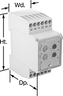
Multifunction Monitoring Relays
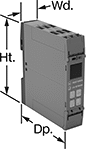 |
Monitor phase, voltage, and frequency at the same time to protect motors, generators, and other three-phase circuits from burning out or overheating. They'll switch the circuit off if they detect voltage or frequencies outside of the set range or phase loss, imbalance, or reversal. Rated IP20, they have recessed terminals that keep fingers and other objects from touching live circuits. Mount them on a 35 mm DIN rail (also known as DIN 3 rail) for fast installation.
These relays use IO-Link, so they can be programmed, monitored, and reset remotely by connecting them to a programmable logic controller (PLC), human-machine interface (HMI), or computer. If you want to program them locally, they have a keypad.
Spring-Clamp-Terminal Wire Connection—Relays with spring-clamp terminals connect and disconnect to wire without screws. Because there’s no screw, these connections are less likely to loosen over time, even in high-vibration environments.
No. of Terminals | Input Voltage, V DC | Trip Voltage, V AC | Input Freq., Hz | Trip Freq., Hz | Trip Time, sec. | Reset Type | Switching Current @ Voltage | Max. Switching Voltage | Adjustment Mechanism | Ht. | Wd. | Dp. | Each | |||
|---|---|---|---|---|---|---|---|---|---|---|---|---|---|---|---|---|
1 Circuit Controlled with 1 Off or 1 On—SPDT | ||||||||||||||||
Screw Terminals with IO-Link | ||||||||||||||||
| 12 | 24 | 90 to 760 | 50, 60 | 15 to 70 | 0.1 to 30 | Automatic | 3 amp @ 240V AC 1 amp @ 24V DC | 400V AC 250V DC | External Controller, Keypad | 3.9" | 0.9" | 3.6" | 8449N12 | 0000000 | ||
Spring-Clamp Terminals with IO-Link | ||||||||||||||||
| 12 | 24 | 90 to 760 | 50, 60 | 15 to 70 | 0.1 to 30 | Automatic | 3 amp @ 240V AC 1 amp @ 24V DC | 400V AC 250V DC | External Controller, Keypad | 3.9" | 0.9" | 3.6" | 8449N11 | 000000 | ||
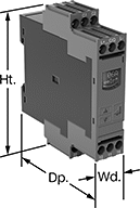
Safety Relays
SIL 2, PLd Max. System Safety Rating—DIN-Rail Mount
 |
Relays that meet SIL 2 are tested for applications with a probability of failure of 0.1% to 1%. They’re often used for emergency shutdowns, and fire, gas, and overpressure detection.
No. of Terminals | Input Voltage | Control Current, mA | Switching Current @ Voltage | Max. Switching Voltage, V AC | Ht. | Wd. | Dp. | Features | Each | |||
|---|---|---|---|---|---|---|---|---|---|---|---|---|
Screw-Terminal Wire Connection | ||||||||||||
4 Circuits Controlled with 2 Off and 2 On—4PST-2NO/2NC | ||||||||||||
| 12 | 120V AC | 10 | 6 amp @ 240V AC | 250 | 3.4" | 0.9" | 3.9" | Interlocked Opposing Contacts, LED Indicator, Recessed Terminals | 6242N114 | 0000000 | ||
| 12 | 24V DC | 42 | 6 amp @ 240V AC | 250 | 3.4" | 0.9" | 3.9" | Interlocked Opposing Contacts, LED Indicator, Recessed Terminals | 6242N115 | 000000 | ||
4 Circuits Controlled with 3 Off and 1 On—4PST-3NO/1NC | ||||||||||||
| 12 | 120V AC | 10 | 6 amp @ 240V AC | 250 | 3.4" | 0.9" | 3.9" | Interlocked Opposing Contacts, LED Indicator, Recessed Terminals | 6242N116 | 000000 | ||
| 12 | 24V DC | 42 | 6 amp @ 240V AC | 250 | 3.4" | 0.9" | 3.9" | Interlocked Opposing Contacts, LED Indicator, Recessed Terminals | 6242N117 | 000000 | ||
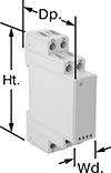
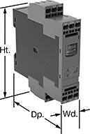
Ground-Fault Monitoring Relays
 |  |
Screw Terminals | Screw Terminals Knob Adjustment |
 |  |
Screw Terminals with IO-Link | Spring-Clamp Terminals with IO-Link |
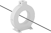
Detect and mitigate ground faults to prevent harm to equipment, circuits, and people. These relays monitor the differential between incoming and outgoing current, also known as residual current. When the balance is off, they trip and cut power to the circuit. These relays are highly sensitive, so you can trust them to de-energize faulty circuits before a minor issue becomes a major one. Rated IP20, they have recessed terminals that keep fingers and other objects from touching live circuits. Mount them on 35 mm DIN rail (also known as DIN 3 rail) for fast installation.
These relays require a current-indicating ring (sold separately) to operate. Choose a ring that is large enough for your lines to pass through. Feed the lines of the circuit through the center of the ring and connect the indicating ring output to the relay.
Spring-Clamp-Terminal Wire Connection—Relays with spring-clamp terminals connect and disconnect to wire without screws. Because they don’t have screws, there’s less of a risk that they will loosen over time, even when they’re under vibration.
IO-Link Communication Protocol—Relays with IO-Link can be programmed, monitored, and reset remotely by connecting them to a programmable logic controller (PLC), human-machine interface (HMI), or computer. If you want to program them locally, they have a keypad.
Knob Adjustment—Relays with knob adjustments have knobs right on the front where you can set your trip current.
LED Indicator—Relays with an LED indicator show the status of your relay, so you know it is wired correctly and when it is actuated.
No. of Terminals | Input Voltage | Trip Current Setting, amp | Trip Current, amp | Trip Time, sec. | Switching Current @ Voltage | Max. Switching Voltage | Adjustment Mechanism | Ht. | Wd. | Dp. | Features | Each | |||
|---|---|---|---|---|---|---|---|---|---|---|---|---|---|---|---|
Screw Terminals | |||||||||||||||
2 Circuits Controlled with 2 Off or 2 On—DPDT | |||||||||||||||
| 12 | 24V AC, 48V AC, 120V AC, 240V AC | 0.03 | — | 0 | 5 amp @ 240V AC 5 amp @ 24V DC | 250V AC 24V DC | — | 3.2" | 1.4" | 2.6" | LED Indicator | 8121N101 | 0000000 | ||
| 12 | 24V AC, 48V AC, 120V AC, 240V AC | 0.3 | — | 0 | 5 amp @ 240V AC 5 amp @ 24V DC | 250V AC 24V DC | — | 3.2" | 1.4" | 2.6" | LED Indicator | 8121N102 | 000000 | ||
| 12 | 24V AC, 48V AC, 120V AC, 240V AC | — | 0.03 to 5 | 0 to 5 | 5 amp @ 240V AC 5 amp @ 24V DC | 250V AC 24V DC | Knob | 3.2" | 1.4" | 2.8" | LED Indicator | 8121N103 | 000000 | ||
| 12 | 24V AC, 48V AC, 120V AC, 240V AC | — | 0.3 to 30 | 0 to 5 | 5 amp @ 240V AC 5 amp @ 24V DC | 250V AC 24V DC | Knob | 3.2" | 1.4" | 2.8" | LED Indicator | 8121N104 | 000000 | ||
Screw Terminals with IO-Link | |||||||||||||||
2 Circuits Controlled with 2 Off or 2 On—DPDT | |||||||||||||||
| 12 | 24V DC | — | 0.03 to 40 | 0 to 999 | 3 amp @ 240V AC 1 amp @ 24V DC | 400V AC 250V DC | External Controller, Keypad | 4" | 0.9" | 3.6" | Remote Reset | 8121N109 | 000000 | ||
Spring-Clamp Terminals with IO-Link | |||||||||||||||
2 Circuits Controlled with 2 Off or 2 On—DPDT | |||||||||||||||
| 12 | 24V DC | — | 0.03 to 40 | 0 to 999 | 3 amp @ 240V AC 1 amp @ 24V DC | 400V AC 250V DC | External Controller, Keypad | 4.1" | 0.9" | 3.6" | Remote Reset | 8121N111 | 000000 | ||