


Filter by
Actuator Style
System of Measurement
Illumination
Position Designation
Input Voltage
Switch Action
Switch Designation
Wire Connection
Switch Starting Position
Electrical Phase
Shaft Diameter
Shaft Length
Panel Cutout Diameter


Electrical Connection
DFARS Specialty Metals
Export Control Classification Number (ECCN)

About Electrical Switches
Choose a switch with the right trigger type, number of inputs, and control functions to power your equipment.
Design-Your-Own Rocker Switches
Illuminated Bases with Quick-Disconnect Terminals for 1 3/4" High × 7/8" Wide Panel Cutouts
 |
On-On—Bases with an on-on position designation alternate power between sets of terminals.
No. of Positions | Position Illuminated | No. of Circuits Controlled | Switch Starting Position | Switch Action | No. of Terminals | Switch Designation | Position Designation | Color | Switching Current @ Voltage | Max. Voltage | Bulb Voltage, V DC | Quick-Disconnect Tab Wd. | Each | ||
|---|---|---|---|---|---|---|---|---|---|---|---|---|---|---|---|
| 2 | Top/Bottom | 1 | 1 Off or 1 On | Maintained | 7 | SPDT | On-On | Black | 15 amp @ 125V AC, 15 amp @ 28V DC | 250V AC, 30V DC | 14 | 0.25" | 1789N53 | 000000 | |
| 3 | Top/Bottom | 1 | 1 Off or 1 On | Maintained | 7 | SPDT | On-Off-On | Black | 15 amp @ 125V AC, 15 amp @ 28V DC | 250V AC, 30V DC | 14 | 0.25" | 1789N54 | 00000 | |
| 3 | Top/Bottom | 1 | 1 Off or 1 On | Momentary | 7 | SPDT | (On)-Off-(On) | Black | 15 amp @ 125V AC, 15 amp @ 28V DC | 250V AC, 30V DC | 14 | 0.25" | 1789N55 | 00000 |
Rotary Switches
For 1/4" Diameter Panel Cutouts |
Control multiple devices with one switch. Turn the shaft to change switch positions. Each position closes a set of contacts per circuit, so you can select between multiple devices on one or more circuits.
Shaft | ||||||||||||
|---|---|---|---|---|---|---|---|---|---|---|---|---|
No. of Circuits Controlled | Switch Action | No. of Positions | No. of Terminals | Dp. Behind Panel | Overall Dia. | Lg. | Dia. | Switching Current @ Voltage | Each | |||
Nickel-Plated Brass with Black Plastic Knob | ||||||||||||
With Solder Turret Terminals for 1/4" Diameter Panel Cutouts | ||||||||||||
| 1 | Maintained | 6 | 7 | 1" | 9/16" | 13/16" | 1/8" | 3 amp @ 125V AC, 2 amp @ 30V DC | 6548K23 | 000000 | ||
Surface-Mount Motor Voltage Monitors
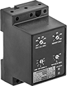 |
Protect electric motors from phase loss, phase reversal, overvoltage, undervoltage, and voltage imbalance. Also known as voltage-monitoring relays, these monitors cut power to a motor when a fault occurs.
Trip Time, sec. | Switching | |||||||||||||
|---|---|---|---|---|---|---|---|---|---|---|---|---|---|---|
Input Voltage Range, V AC | No. of Terminals | Control Power, W | Voltage Imbalance Adjustment | Automatic Reset | Delayed Automatic Reset | Current, amp | Voltage, V AC | Ht. | Wd. | Certification | Each | |||
1 Circuit Controlled with 1 Off or 1 On—SPDT | ||||||||||||||
For Three Phase | ||||||||||||||
| 190 to 480 | 7 | 6 | 2% to 8% | 1 to 30 | 1 to 500 | 10 | 240 | 3.5" | 2.08" | UL Listed | 7632K72 | 0000000 | ||
| 475 to 600 | 7 | 6 | 2% to 8% | 1 to 30 | 1 to 500 | 10 | 240 | 3.5" | 2.08" | UL Listed | 7632K74 | 000000 | ||
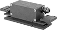
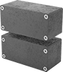
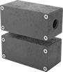
Tamper-Resistant Magnetic Contact Alarm Switches
 |  |  |
Flush Mount | Surface Mount | Surface Mount with Conduit Connection |
Prevent unauthorized use of doors or windows with a combination of coded magnets and contacts that wire to an alarm system. The coded magnets mean they can’t be bypassed with regular magnets. These switches actuate when the magnet comes within sensing distance of the switch and reset when the magnet moves away. Mount the magnet to your door or window and the switch to the frame. Connect the switch contacts to an alarm system, which will trigger when the magnet is pulled away as your door or window is opened.
Flush Mount—Flush-mount switches are designed to mount against the door jam. They have a cord grip to reduce strain on your cord.
Surface Mount—Surface-mount switches mount on the surface of your door.
Conduit Trade Size 1/2—Switches with a 1/2 conduit connection are ready to directly attach to your conduit.
No. of Circuits Controlled | Switch Starting Position | Switch Designation | Switching Current @ Voltage | Max. Sensing Distance | No. of Terminals | Conduit Trade Size | Lg. | Wd. | Ht. | Features | Enclosure Rating | Each | |||
|---|---|---|---|---|---|---|---|---|---|---|---|---|---|---|---|
Painted Zinc Housing with Screw Terminals | |||||||||||||||
Screw On—Flush Mount | |||||||||||||||
| 2 | 1 Off and 1 On | DPST-1NO/1NC | 0.2 amp @ 30V DC | 0.26" | 7 | — | 4.33" | 1.38" | 1.26" | Auxiliary NO (Normally Open) Alarm, Nickel-Plated Brass Cord Grip | IP67 | 7612N13 | 0000000 | ||
Screw On—Surface Mount | |||||||||||||||
| 2 | 1 Off and 1 On | DPST-1NO/1NC | 0.2 amp @ 30V DC | 0.26" | 7 | — | 2.96" | 1.38" | 1.34" | Auxiliary NO (Normally Open) Alarm | IP67 | 7612N12 | 000000 | ||
| 2 | 1 Off and 1 On | DPST-1NO/1NC | 0.2 amp @ 30V DC | 0.26" | 7 | 1/2 | 2.96" | 1.38" | 1.34" | Auxiliary NO (Normally Open) Alarm | IP67 | 7612N11 | 000000 | ||
Solid State Surface-Mount Timer Relays
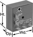 |
Attach these relays to a flat surface using the mounting hole. They have no moving parts, so compared to mechanical switches, they require less maintenance, last longer, and are quieter.
Delayed Switch Off (Delay on Break)—Delayed switch off (delay on break) relays activate with a switch instead of input voltage. When the switch is turned off, the relay remains on for a programmed amount of time before turning off. For example, a projector’s light is turned off with a switch, but its cooling fan continues to run for a set time.
Repeat Cycle—Repeat cycle relays turn on for a duration, then off for the same duration. They alternate between the two cycles until input voltage is removed. A common example would be a flashing light.
Switch on (Single Shot)—Switch on (single shot) relays require a switch to activate the relay. They’ll stay on for a programmed amount of time. For example, lights in a storage room are turned on with a switch and stay on for a set time before turning off.
Timing Range | ||||||||||||
|---|---|---|---|---|---|---|---|---|---|---|---|---|
No. of Terminals | Input Voltage | Control Current, mA | No. of | Overall, sec. | Switching Current @ Voltage | Ht. | Wd. | Dp. | Each | |||
Delayed Switch Off (Delay on Break) | ||||||||||||
1 Circuit Controlled with 1 Off—SPST-NO | ||||||||||||
| 7 | 12V DC | 217 | 1 | 0.25 to 5 | 1 amp @ 120V AC | 2" | 2" | 0.88" | 7457K522 | 000000 | ||
| 7 | 12V DC | 217 | 1 | 3 to 60 | 1 amp @ 120V AC | 2" | 2" | 0.88" | 7457K524 | 00000 | ||
Repeat Cycle | ||||||||||||
1 Circuit Controlled with 1 Off—SPST-NO | ||||||||||||
| 7 | 120V AC | 36 | 1 | 0.05 to 1 | 1 amp @ 120V AC | 2" | 2" | 0.88" | 7457K661 | 000000 | ||
| 7 | 120V AC | 36 | 1 | 3 to 60 | 1 amp @ 120V AC | 2" | 2" | 0.88" | 7457K664 | 000000 | ||
| 7 | 120V AC | 36 | 1 | 30 to 10 | 1 amp @ 120V AC | 2" | 2" | 0.88" | 7457K666 | 000000 | ||
Switch on (Single Shot) | ||||||||||||
1 Circuit Controlled with 1 Off—SPST-NO | ||||||||||||
| 7 | 12V DC | 217 | 1 | 0.25 to 5 | 1 amp @ 120V AC | 2" | 2" | 0.88" | 7457K512 | 00000 | ||
| 7 | 12V DC | 217 | 1 | 0.5 to 10 | 1 amp @ 120V AC | 2" | 2" | 0.88" | 7457K513 | 00000 | ||
| 7 | 12V DC | 217 | 1 | 3 to 60 | 1 amp @ 120V AC | 2" | 2" | 0.88" | 7457K514 | 00000 | ||
