



























Filter by
Product Family
Switching Current

Switching Voltage
Actuator Style


Switch Action
Switch Starting Position
Mounting Location
Switch Type

Toggle Type
U.S.–Mexico–Canada Agreement (USMCA) Qualifying
Export Control Classification Number (ECCN)
DFARS Specialty Metals

About Electrical Switches
%20--%3e%3csvg%20version='1.1'%20id='Layer_1'%20xmlns='http://www.w3.org/2000/svg'%20xmlns:xlink='http://www.w3.org/1999/xlink'%20x='0px'%20y='0px'%20viewBox='0%200%20400%20400'%20style='enable-background:new%200%200%20400%20400;'%20xml:space='preserve'%3e%3cstyle%20type='text/css'%3e%20.st0{fill:%231A70A0;}%20.st1{opacity:0.5;}%20%3c/style%3e%3cg%3e%3cg%3e%3cpath%20class='st0'%20d='M200,56.9c38.35,0,74.4,14.93,101.51,42.05c27.11,27.11,42.05,63.17,42.05,101.51s-14.93,74.4-42.05,101.51%20S238.35,344.02,200,344.02s-74.4-14.93-101.51-42.05c-27.11-27.11-42.05-63.17-42.05-101.51s14.93-74.4,42.05-101.51%20S161.65,56.9,200,56.9%20M200,12.9C96.41,12.9,12.44,96.88,12.44,200.46c0,103.59,83.97,187.56,187.56,187.56%20c103.59,0,187.56-83.97,187.56-187.56C387.56,96.88,303.59,12.9,200,12.9L200,12.9z'/%3e%3c/g%3e%3cg%3e%3cg%20class='st1'%3e%3cpath%20class='st0'%20d='M235.49,152.24h16.15l-27.46,111.87c-1.94,7.8-2.91,12.5-2.91,14.1c0,1.82,0.58,3.29,1.73,4.41%20c1.16,1.12,2.69,1.68,4.61,1.68c5.23,0,11.78-3.85,19.63-11.55l17.22,21.34c-16.95,17.33-34.87,26-53.78,26%20c-8.37,0-15.45-1.47-21.23-4.41c-5.79-2.94-10.44-7.25-13.95-12.92c-3.51-5.67-5.27-11.18-5.27-16.53c0-1.93,0.35-5.24,1.05-9.94%20c1-6.94,2.05-12.54,3.15-16.82l15.22-62.15h-32.69l7.65-30.97C190.89,163.58,214.53,158.88,235.49,152.24z%20M230.44,80.84%20c8.24,0,14.66,2.62,19.26,7.86c4.6,5.24,6.9,11.55,6.9,18.94c0,5.46-1.42,10.7-4.25,15.73c-2.83,5.03-6.88,9.07-12.12,12.12%20c-5.24,3.05-10.33,4.57-15.24,4.57c-4.6,0-9.17-1.23-13.72-3.69c-4.55-2.46-8.02-5.78-10.43-9.95%20c-2.41-4.17-3.61-8.67-3.61-13.48c0-5.35,1.52-10.64,4.57-15.89c3.05-5.24,7.03-9.25,11.96-12.04%20C218.68,82.23,224.24,80.84,230.44,80.84z'/%3e%3c/g%3e%3cg%3e%3cpath%20class='st0'%20d='M214.08,152.24h16.15l-27.46,111.87c-1.94,7.8-2.91,12.5-2.91,14.1c0,1.82,0.58,3.29,1.73,4.41%20c1.16,1.12,2.69,1.68,4.61,1.68c5.23,0,11.78-3.85,19.63-11.55l17.22,21.34c-16.95,17.33-34.87,26-53.78,26%20c-8.37,0-15.45-1.47-21.23-4.41c-5.79-2.94-10.44-7.25-13.95-12.92c-3.51-5.67-5.27-11.18-5.27-16.53c0-1.93,0.35-5.24,1.05-9.94%20c1-6.94,2.05-12.54,3.15-16.82l15.22-62.15h-32.69l7.65-30.97C169.48,163.58,193.11,158.88,214.08,152.24z%20M209.03,80.84%20c8.24,0,14.66,2.62,19.26,7.86c4.6,5.24,6.9,11.55,6.9,18.94c0,5.46-1.42,10.7-4.25,15.73c-2.83,5.03-6.88,9.07-12.12,12.12%20c-5.24,3.05-10.33,4.57-15.24,4.57c-4.6,0-9.17-1.23-13.72-3.69c-4.55-2.46-8.02-5.78-10.43-9.95%20c-2.41-4.17-3.61-8.67-3.61-13.48c0-5.35,1.52-10.64,4.57-15.89c3.05-5.24,7.03-9.25,11.96-12.04%20C197.26,82.23,202.83,80.84,209.03,80.84z'/%3e%3c/g%3e%3c/g%3e%3c/g%3e%3c/svg%3e)
Choose a switch with the right trigger type, number of inputs, and control functions to power your equipment.
Toggle Switches
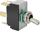 | 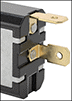 | 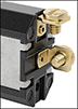 | 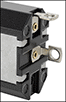 |
Rounded Toggle | Quick-Disconnect-Terminal Wire Connection | Screw-Terminal Wire Connection | Tab Wire Connection |
No. of Circuits Controlled | Switch Starting Position | Switch Action | No. of Terminals | Switch Designation | Position Designation | Switching Current @ Voltage | Max. Voltage | For Max. Panel Thk. | Mounting Hardware Included | Mounting Thread Size | Choose a Wire Connection | Each | |||
|---|---|---|---|---|---|---|---|---|---|---|---|---|---|---|---|
2 Position with Rounded Toggle | |||||||||||||||
For 1/2" Diameter Panel Cutouts | |||||||||||||||
| 3 | 3 Off or 3 On | Maintained | 9 | 3PDT | On-On | 15 amp @ 125V AC/28V DC | 28V DC 250V AC | 0.13" | Yes | 15/32"-32 | Quick-Disconnect Terminal, Screw Terminal, Tab | 7343K861 | 000000 | ||
3 Position with Rounded Toggle | |||||||||||||||
For 1/2" Diameter Panel Cutouts | |||||||||||||||
| 3 | 3 Off or 3 On | Maintained | 9 | 3PDT | On-Off-On | 15 amp @ 125V AC/28V DC | 28V DC 250V AC | 0.13" | Yes | 15/32"-32 | Quick-Disconnect Terminal, Screw Terminal, Tab | 7343K851 | 00000 | ||
Cam Panel-Mount Lever Switches
 |
Lever Switches | Legend Plates | |||||||||||||||
|---|---|---|---|---|---|---|---|---|---|---|---|---|---|---|---|---|
Lever Lg. | No. of Circuits Controlled | Switch Action | No. of Terminals | Position Designation | Message | Switching Current @ Voltage | Max. Voltage | Dia. | Dp. Behind Panel | Each | Message | Each | ||||
3 Positions for 3/8" and 10 mm Diameter Panel Cutouts | ||||||||||||||||
Changeover with Screw Terminals | ||||||||||||||||
| 1 1/2" | 3 | Maintained | 9 | On-Off-On | 1-0-2 | 12 amp @ 600V AC | 600V AC 600V DC | 1 1/8" | 2 3/16" | 6958N17 | 000000 | Hand-Off-Auto | 6958N41 | 000000 | ||
| 1 3/4" | 3 | Maintained | 9 | On-Off-On | 1-0-2 | 50 amp @ 600V AC | 600V AC 600V DC | 1 1/8" | 3 15/16" | 6958N36 | 000000 | Hand-Off-Auto | 6958N43 | 00000 | ||
| 1 3/4" | 3 | Maintained | 9 | On-Off-On | 1-0-2 | 63 amp @ 600V AC | 600V AC 600V DC | 1 1/8" | 3 15/16" | 6958N38 | 000000 | Hand-Off-Auto | 6958N43 | 00000 | ||
| 1 13/16" | 3 | Maintained | 9 | On-Off-On | 1-0-2 | 20 amp @ 600V AC | 600V AC 600V DC | 1 1/8" | 2 1/4" | 6958N19 | 00000 | Hand-Off-Auto | 6958N41 | 00000 | ||
| 1 13/16" | 3 | Maintained | 9 | On-Off-On | 1-0-2 | 25 amp @ 600V AC | 600V AC 600V DC | 1 1/8" | 2 9/16" | 6958N22 | 000000 | Hand-Off-Auto | 6958N41 | 00000 | ||
Selector with Screw Terminals | ||||||||||||||||
| 1 1/2" | 3 | Maintained | 9 | Off-on-On | 0-1-2 | 12 amp @ 600V AC | 600V AC 600V DC | 1 1/8" | 2 3/16" | 6958N24 | 00000 | — | ——— | 0 | ||
| 1 13/16" | 3 | Maintained | 9 | Off-on-On | 0-1-2 | 20 amp @ 600V AC | 600V AC 600V DC | 1 1/8" | 2 1/4" | 6958N26 | 00000 | — | ——— | 0 | ||
| 1 13/16" | 3 | Maintained | 9 | Off-on-On | 0-1-2 | 25 amp @ 600V AC | 600V AC 600V DC | 1 1/8" | 2 9/16" | 6958N28 | 000000 | — | ——— | 0 | ||
High-Current Toggle Switches
 |
Able to withstand high currents, these switches are often used with motors and pumps.
On-On—Switches with an on-on position designation alternate power between sets of terminals.
No. of Circuits Controlled | Switch Starting Position | Switch Action | No. of Terminals | Switch Designation | Position Designation | Switching Current @ Voltage | Max. Voltage | Dp. Behind Panel | Mounting Hardware Included | Each | |||
|---|---|---|---|---|---|---|---|---|---|---|---|---|---|
2 Position with Quick-Disconnect Terminals | |||||||||||||
For 1/2" Diameter Panel Cutouts | |||||||||||||
| 3 | 3 Off or 3 On | Maintained | 9 | 3PDT | On-On | 20 amp @ 125V AC, 20 amp @ 30V DC | 30V DC 250V AC | 1.31" | Yes | 8001K41 | 000000 | ||
2 Position with Screw Terminals | |||||||||||||
For 1/2" Diameter Panel Cutouts | |||||||||||||
| 3 | 3 Off or 3 On | Maintained | 9 | 3PDT | On-On | 30 amp @ 125V AC/30V DC | 30V DC 250V AC | 1.34" | Yes | 8001K14 | 00000 | ||
3 Position with Quick-Disconnect Terminals | |||||||||||||
For 1/2" Diameter Panel Cutouts | |||||||||||||
| 3 | 3 Off or 3 On | Maintained | 9 | 3PDT | On-Off-On | 20 amp @ 125V AC, 20 amp @ 30V DC | 30V DC 250V AC | 1.31" | Yes | 8001K42 | 00000 | ||
3 Position with Screw Terminals | |||||||||||||
For 1/2" Diameter Panel Cutouts | |||||||||||||
| 3 | 3 Off or 3 On | Maintained | 9 | 3PDT | On-Off-On | 30 amp @ 125V AC/30V DC | 30V DC 250V AC | 1.34" | Yes | 8001K15 | 00000 | ||
3 Position with Tab | |||||||||||||
For 1/2" Diameter Panel Cutouts | |||||||||||||
| 3 | 3 Off or 3 On | Maintained | 9 | 3PDT | On-Off-On | 20 amp @ 125V AC, 20 amp @ 30V DC | 30V DC 250V AC | 1.08" | Yes | 8001K35 | 00000 | ||
Miniature Toggle Switches
 |
Maximize the space in a panel—these switches are half the size of most toggle switches.
On-On—Switches with an on-on or on-(on) position designation alternate power between sets of terminals.
No. of Circuits Controlled | Switch Starting Position | Switch Action | No. of Terminals | Switch Designation | Position Designation | Switching Current @ Voltage | Max. Voltage | For Max. Panel Thk. | Mounting Hardware Included | Mounting Thread Size | Wire Connection | Each | |||
|---|---|---|---|---|---|---|---|---|---|---|---|---|---|---|---|
2 Position with Rounded Toggle | |||||||||||||||
For 1/4" Diameter Panel Cutouts | |||||||||||||||
| 3 | 3 Off or 3 On | Maintained | 9 | 3PDT | On-On | 6 amp @ 125V AC, 4 amp @ 30V DC | 30V DC 250V AC | 0.16" | Yes | 1/4"-40 | Tab | 7347K96 | 000000 | ||
Rotary Switches
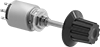 |
For 1/4" Diameter Panel Cutouts |
Control multiple devices with one switch. Turn the shaft to change switch positions. Each position closes a set of contacts per circuit, so you can select between multiple devices on one or more circuits.
Shaft | ||||||||||||
|---|---|---|---|---|---|---|---|---|---|---|---|---|
No. of Circuits Controlled | Switch Action | No. of Positions | No. of Terminals | Dp. Behind Panel | Overall Dia. | Lg. | Dia. | Switching Current @ Voltage | Each | |||
Nickel-Plated Brass with Black Plastic Knob | ||||||||||||
With Solder Pin Terminals for 1/4" Diameter Panel Cutouts | ||||||||||||
| 1 | Maintained | 8 | 9 | 1 1/16" | 9/16" | 13/16" | 1/8" | 2 amp @ 125V AC, 1 amp @ 30V DC | 6548K21 | 000000 | ||
Foot Switches
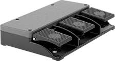 | 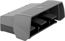 |
Back Pivot with 3 Pedals | Back Pivot with 3 Pedals and Guard |
No. of Circuits Controlled | Switch Starting Position | Switch Action | Switch Designation | Switching Current @ Voltage | Housing Material | Wire Connection | No. of Terminals | Each | |||
|---|---|---|---|---|---|---|---|---|---|---|---|
1 Speed | |||||||||||
Back Pivot with 3 Pedals | |||||||||||
| 3 | 1 Off or 1 On | Momentary | SPDT | 3 amp @ 240V AC | Aluminum | Screw Terminal | 9 | 7829N12 | 000000000 | ||
Back Pivot with 3 Pedals and Guard | |||||||||||
| 3 | 1 Off or 1 On | Momentary | SPDT | 3 amp @ 240V AC | Aluminum | Screw Terminal | 9 | 7829N11 | 00000000 | ||
Latching Relays
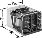 | 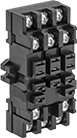 |
9 Terminals | 9-Terminal Relay Socket |
Relays | Relay Sockets | |||||||||||||
|---|---|---|---|---|---|---|---|---|---|---|---|---|---|---|
No. of Terminals | Input Voltage | Control Current, mA | Switching Current @ Voltage | hp @ Switching Voltage | Ht. | Wd. | Dp. | Quick-Disconnect Tab Wd. | Each | Each | ||||
2 Circuits Controlled with 2 Off or 2 On—DPDT | ||||||||||||||
| 9 | 24V AC | 70 | 10 amp @ 240V AC/24V DC | 1/3 hp @ 120V AC 1/2 hp @ 240V AC | 1.4" | 1.5" | 1.9" | 0.187" | 1358T11 | 000000 | 1358T21 | 000000 | ||
| 9 | 120V AC | 14 | 10 amp @ 240V AC/24V DC | 1/3 hp @ 120V AC 1/2 hp @ 240V AC | 1.4" | 1.5" | 1.9" | 0.187" | 1358T12 | 00000 | 1358T21 | 00000 | ||
| 9 | 12V DC | 100 | 10 amp @ 240V AC/24V DC | 1/3 hp @ 120V AC 1/2 hp @ 240V AC | 1.4" | 1.5" | 1.9" | 0.187" | 1358T13 | 00000 | 1358T21 | 00000 | ||
| 9 | 24V DC | 50 | 10 amp @ 240V AC/24V DC | 1/3 hp @ 120V AC 1/2 hp @ 240V AC | 1.4" | 1.5" | 1.9" | 0.187" | 1358T14 | 00000 | 1358T21 | 00000 | ||
Analog-Input Proportional-Control Relays
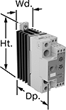 |
1 Circuit Controlled |
Often used to regulate the speed of AC fans or keep a heater at a set temperature, these relays connect directly to sensors to calculate and adjust output power. This allows you to use an analog input without converting it to a digital signal to control output power. They are solid state and have no moving parts, so they require less maintenance and last longer, are quieter, and switch faster than mechanical relays. IP20 rated, they have recessed terminals that prevent fingers and other objects from touching live circuits. An integrated heat sink disperses heat to increase the relay’s current rating. The LED indicator shows input voltage loss and internal relay faults, so you can easily check that your system is operating properly.
Mount them on 35 mm DIN rail (also known as DIN 3 rail) for fast installation. They also mount to flat surfaces.
All relays have phase-angle switching to accurately control all types of loads. This mode signals at non-zero voltage, which can produce electrical noise.
Single Phase—Single-phase relays can be set to switch every 1, 4, or 16 cycles. When used with infrared heaters, they have an option to switch at the half cycle and again at the full cycle. When switching at 16 cycles or at the half cycle, these relays have a soft-start option to increase the output slower in high-inrush current applications.
Potentiometer Input—Relays with a potentiometer input can connect to an external potentiometer for manual control.
Input | Output | |||||||||||||||
|---|---|---|---|---|---|---|---|---|---|---|---|---|---|---|---|---|
No. of Terminals | Analog Signal | No. of | Voltage, V AC | Current, amp | No. of | Control Current, mA | Switching Current @ Voltage | Max. Switching Voltage, V AC | Ht. | Wd. | Dp. | Features | Each | |||
1 Circuit Controlled with 1 Off—SPST-NO | ||||||||||||||||
Single Phase with Phase Angle Switching Mode | ||||||||||||||||
| 9 | 0V DC to 10V DC | 1 | 85 to 265 | 30 | 1 | 50 | 30 amp @ 230V AC | 265 | 4.33" | 1.4" | 4.08" | Integrated Heat Sink, LED Indicator, Recessed Terminals, Potentiometer Input | 7048N15 | 0000000 | ||
| 9 | 0V DC to 10V DC | 1 | 85 to 265 | 42 | 1 | 50 | 42 amp @ 230V AC | 265 | 4.33" | 1.4" | 4.08" | Integrated Heat Sink, LED Indicator, Recessed Terminals, Potentiometer Input | 7048N16 | 000000 | ||
| 9 | 0V DC to 10V DC | 1 | 190 to 550 | 30 | 1 | 50 | 30 amp @ 480V AC | 550 | 4.33" | 1.4" | 4.08" | Integrated Heat Sink, LED Indicator, Recessed Terminals, Potentiometer Input | 7048N17 | 000000 | ||
| 9 | 0V DC to 10V DC | 1 | 190 to 550 | 42 | 1 | 50 | 42 amp @ 480V AC | 550 | 4.33" | 1.4" | 4.08" | Integrated Heat Sink, LED Indicator, Recessed Terminals, Potentiometer Input | 7048N18 | 000000 | ||
Current-Monitoring Relays
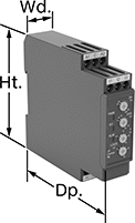 | 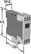 | 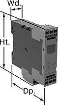 |
Screw Terminals Knob Adjustment | Screw Terminals with IO-Link, Keypad Adjustment | Spring-Clamp Terminals with IO-Link, Keypad Adjustment |
Protect electrical equipment from overcurrent and undercurrent damage—these relays continuously monitor current flow. When current is outside a set range, they trip and cut power to prevent overheating, fire hazards, and stalling. Rated IP20, these relays have recessed terminals that keep fingers and other objects from touching live circuits. Mount them on a 35 mm DIN rail (also known as DIN 3 rail) for fast installation.
Spring-Clamp-Terminal Wire Connection—Relays with spring-clamp terminals connect and disconnect to wire without screws. Because there’s no screw, these connections are less likely to loosen over time, even in high-vibration environments.
IO-Link Communication Protocol—Relays with IO-Link can be programmed, monitored, and reset remotely by connecting them to a programmable logic controller (PLC), human-machine interface (HMI), or computer. If you want to program them locally, they have a keypad.
Knob Adjustment—Relays with knob adjustments have knobs right on the front where you can set your trip current. You can see that they're wired correctly and when they're actuated based on the LED indicators.
No. of Terminals | Input Voltage | Trip Current Setting, amp | Trip Current, amp | Trip Time, sec. | Reset Type | Switching Current @ Voltage | Max. Switching Voltage | Adjustment Mechanism | Ht. | Wd. | Dp. | Digital Display Type | Each | |||
|---|---|---|---|---|---|---|---|---|---|---|---|---|---|---|---|---|
Screw Terminals | ||||||||||||||||
1 Circuit Controlled with 1 Off or 1 On—SPDT | ||||||||||||||||
| 9 | 24V AC, 24V DC | 0.1 to 1, 0.5 to 5, 0.8 to 8 | — | 0.1 to 30 | Automatic, Manual | 5 amp @ 240V AC 5 amp @ 30V DC | 250V AC 30V DC | Knob | 3.5" | 0.9" | 3.9" | — | 8123N14 | 0000000 | ||
| 9 | 120V AC, 240V AC | 0.1 to 1, 0.5 to 5, 0.8 to 8 | — | 0.1 to 30 | Automatic, Manual | 5 amp @ 240V AC 5 amp @ 30V DC | 250V AC 30V DC | Knob | 3.5" | 0.9" | 3.9" | — | 8123N13 | 000000 | ||
Screw Terminals with IO-Link | ||||||||||||||||
1 Circuit Controlled with 1 Off or 1 On—SPDT | ||||||||||||||||
| 9 | 24V DC | — | 0.05 to 10 | 0 to 999 | Automatic | 3 amp @ 240V AC 1 amp @ 24V DC | 400V AC 250V DC | External Controller, Keypad | 3.6" | 0.9" | 3.4" | LCD | 8123N11 | 000000 | ||
Spring-Clamp Terminals with IO-Link | ||||||||||||||||
1 Circuit Controlled with 1 Off or 1 On—SPDT | ||||||||||||||||
| 9 | 24V DC | — | 0.05 to 10 | 0 to 999 | Automatic | 3 amp @ 240V AC 1 amp @ 24V DC | 400V AC 250V DC | External Controller, Keypad | 3.8" | 0.9" | 3.4" | LCD | 8123N12 | 000000 | ||
Smart DIN-Rail Mount Multifunction Timer Relays
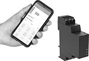 |
2 Circuits Controlled |
No. of Terminals | Input Voltage | Control Power, W | Timer Relay Function | Overall Timing Range | Switching Current @ Voltage | Max. Switching Voltage, V AC | Ht. | Wd. | Dp. | Operating System Compatibility | Features | Each | |||
|---|---|---|---|---|---|---|---|---|---|---|---|---|---|---|---|
2 Circuits Controlled with 2 Off or 2 On—DPDT | |||||||||||||||
| 9 | 24V AC, 48V AC, 120V AC, 240V AC, 24V DC, 48V DC, 60V DC, 120V DC, 240V DC | 0.6 | Manual Switch Control Fixed On/Off Switch on (Single Shot) Delayed Start (Delay on Make) Delayed Switch Off (Delay on Break) Delayed Switch-On with Delayed Switch-Off Interval Repeat Cycle Asymmetrical Repeat Cycle Switch-On Asymmetrical Repeat Cycle Star-to-Delta | 0.1 sec. to 999 hr. | 8 amp @ 240V AC | 250 | 3.5" | 0.9" | 2.9" | Android 4.4 or Later, iOS 14.5 or Later | LED Indicator | 8491N11 | 000000 | ||
Voltage-Monitoring Relays
Monitoring Relays
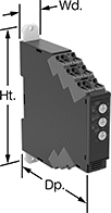 |
With Spring-Clamp Terminals—Relays with spring-clamp terminals connect and disconnect to wire without screws. Because there’s no screw, these connections are less likely to loosen over time, even in high-vibration environments.
Knob Adjustment—Relays with knob adjustments have knobs right on the front where you can set your trip voltage. You can see that they're wired correctly and when they're actuated based on the LED indicators. If you want to mount these relays to a surface instead of DIN rail, they have mounting holes.
No. of Terminals | Input Voltage | Trip Voltage Setting | Trip Time, sec. | Reset Type | Switching Current @ Voltage | Max. Switching Voltage | Adjustment Mechanism | Ht. | Wd. | Dp. | Features | Each | |||
|---|---|---|---|---|---|---|---|---|---|---|---|---|---|---|---|
1 Circuit Controlled with 1 Off or 1 On—SPDT | |||||||||||||||
With Spring-Clamp Terminals | |||||||||||||||
| 9 | 24V AC, 24V DC | 1V AC to 10V AC 3V AC to 30V AC 15V AC to 150V AC 1V DC to 10V DC 3V DC to 30V DC 15V DC to 150V DC | 0.1 to 30 | Automatic, Manual | 5 amp @ 240V AC 5 amp @ 30V DC | 250V AC 48V DC | Knob | 3.5" | 0.7" | 3.5" | LED Indicator | 8446N101 | 0000000 | ||
| 9 | 24V AC, 24V DC | 20V AC to 200V AC 30V AC to 300V AC 60V AC to 600V AC 20V DC to 200V DC 30V DC to 300V DC 60V DC to 600V DC | 0.1 to 30 | Automatic, Manual | 5 amp @ 240V AC 5 amp @ 30V DC | 250V AC 48V DC | Knob | 3.5" | 0.7" | 3.5" | LED Indicator | 8446N103 | 000000 | ||
| 9 | 120V AC, 240V AC | 1V AC to 10V AC 3V AC to 30V AC 15V AC to 150V AC 1V DC to 10V DC 3V DC to 30V DC 15V DC to 150V DC | 0.1 to 30 | Automatic, Manual | 5 amp @ 240V AC 5 amp @ 30V DC | 250V AC 48V DC | Knob | 3.5" | 0.7" | 3.5" | LED Indicator | 8446N102 | 000000 | ||
| 9 | 120V AC, 240V AC | 20V AC to 200V AC 30V AC to 300V AC 60V AC to 600V AC 20V DC to 200V DC 30V DC to 300V DC 60V DC to 600V DC | 0.1 to 30 | Automatic, Manual | 5 amp @ 240V AC 5 amp @ 30V DC | 250V AC 48V DC | Knob | 3.5" | 0.7" | 3.5" | LED Indicator | 8446N104 | 000000 | ||
Monitoring Relays with IO-Link
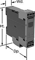 |
Relays with IO-Link can be programmed, monitored and reset remotely by connecting them to a programmable logic controller (PLC), human-machine interface (HMI), or computer. If you want to program them locally, they have a keypad.
With Spring-Clamp Terminals—Relays with spring-clamp terminals connect and disconnect to wire without screws. Because there’s no screw, these connections are less likely to loosen over time, even in high-vibration environments.
No. of Terminals | Input Voltage, V DC | Trip Voltage | Trip Time, sec. | Reset Type | Switching Current @ Voltage | Max. Switching Voltage | Adjustment Mechanism | Ht. | Wd. | Dp. | Digital Display Type | Features | Each | |||
|---|---|---|---|---|---|---|---|---|---|---|---|---|---|---|---|---|
1 Circuit Controlled with 1 Off or 1 On—SPDT | ||||||||||||||||
With Screw Terminals | ||||||||||||||||
| 9 | 24 | 10V AC to 600V AC, 10V DC to 600V DC | 0 to 999 | Automatic | 3 amp @ 240V AC 1 amp @ 24V DC | 400V AC 250V DC | External Controller, Keypad | 3.6" | 0.9" | 3.6" | LCD | Remote Reset | 8446N105 | 0000000 | ||
With Spring-Clamp Terminals | ||||||||||||||||
| 9 | 24 | 10V AC to 600V AC, 10V DC to 600V DC | 0 to 999 | Automatic | 3 amp @ 240V AC 1 amp @ 24V DC | 400V AC 250V DC | External Controller, Keypad | 3.8" | 0.9" | 3.6" | LCD | Remote Reset | 8446N106 | 000000 | ||
Frequency-Monitoring Relays
 |
DIN-Rail Mount |
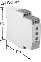
Prevent changes in frequency from damaging sensitive equipment. Often used with motors, fluorescent lighting, and controllers, these relays cut power to your device if the frequency falls outside the set range. Switches on the front of these relays let you set your trip frequency and time. You can see that they're wired correctly and when they're actuated based on the LED indicators. Rated IP20, these relays have recessed terminals that keep fingers and other objects from touching live circuits.
DIN-Rail Mount—DIN-rail mount relays snap onto 35 mm DIN rail (also known as DIN 3 rail) for fast installation.
Trip Frequency Setting, Hz | ||||||||||||||||
|---|---|---|---|---|---|---|---|---|---|---|---|---|---|---|---|---|
No. of Terminals | Input Voltage, V AC | 50 Hz Input | 60 Hz Input | Trip Time, sec. | Reset Type | Switching Current @ Voltage | Max. Switching Voltage | Adjustment Mechanism | Ht. | Wd. | Dp. | Features | Each | |||
1 Circuit Controlled with 1 Off or 1 On—SPDT | ||||||||||||||||
DIN-Rail Mount | ||||||||||||||||
| 9 | 24, 48, 120, 240 | 40 to 60 48 to 52 | 50 to 70 58 to 62 | 0.1 to 30 | Automatic, Manual | 8 amp @ 240V AC 5 amp @ 24V DC | 250V AC 24V DC | DIP Switch | 3.1" | 0.9" | 3.9" | LED Indicator | 8477N11 | 0000000 | ||
