



























Filter by
Switch Designation
Switch Action
Voltage

Actuator Style


Switch Starting Position
Wire Connection
Environment
Electrical Connection


Number of Positions
Number of Buttons
Panel Cutout Diameter
Toggle Type
DFARS Specialty Metals
Export Control Classification Number (ECCN)

About Electrical Switches
%20--%3e%3csvg%20version='1.1'%20id='Layer_1'%20xmlns='http://www.w3.org/2000/svg'%20xmlns:xlink='http://www.w3.org/1999/xlink'%20x='0px'%20y='0px'%20viewBox='0%200%20400%20400'%20style='enable-background:new%200%200%20400%20400;'%20xml:space='preserve'%3e%3cstyle%20type='text/css'%3e%20.st0{fill:%231A70A0;}%20.st1{opacity:0.5;}%20%3c/style%3e%3cg%3e%3cg%3e%3cpath%20class='st0'%20d='M200,56.9c38.35,0,74.4,14.93,101.51,42.05c27.11,27.11,42.05,63.17,42.05,101.51s-14.93,74.4-42.05,101.51%20S238.35,344.02,200,344.02s-74.4-14.93-101.51-42.05c-27.11-27.11-42.05-63.17-42.05-101.51s14.93-74.4,42.05-101.51%20S161.65,56.9,200,56.9%20M200,12.9C96.41,12.9,12.44,96.88,12.44,200.46c0,103.59,83.97,187.56,187.56,187.56%20c103.59,0,187.56-83.97,187.56-187.56C387.56,96.88,303.59,12.9,200,12.9L200,12.9z'/%3e%3c/g%3e%3cg%3e%3cg%20class='st1'%3e%3cpath%20class='st0'%20d='M235.49,152.24h16.15l-27.46,111.87c-1.94,7.8-2.91,12.5-2.91,14.1c0,1.82,0.58,3.29,1.73,4.41%20c1.16,1.12,2.69,1.68,4.61,1.68c5.23,0,11.78-3.85,19.63-11.55l17.22,21.34c-16.95,17.33-34.87,26-53.78,26%20c-8.37,0-15.45-1.47-21.23-4.41c-5.79-2.94-10.44-7.25-13.95-12.92c-3.51-5.67-5.27-11.18-5.27-16.53c0-1.93,0.35-5.24,1.05-9.94%20c1-6.94,2.05-12.54,3.15-16.82l15.22-62.15h-32.69l7.65-30.97C190.89,163.58,214.53,158.88,235.49,152.24z%20M230.44,80.84%20c8.24,0,14.66,2.62,19.26,7.86c4.6,5.24,6.9,11.55,6.9,18.94c0,5.46-1.42,10.7-4.25,15.73c-2.83,5.03-6.88,9.07-12.12,12.12%20c-5.24,3.05-10.33,4.57-15.24,4.57c-4.6,0-9.17-1.23-13.72-3.69c-4.55-2.46-8.02-5.78-10.43-9.95%20c-2.41-4.17-3.61-8.67-3.61-13.48c0-5.35,1.52-10.64,4.57-15.89c3.05-5.24,7.03-9.25,11.96-12.04%20C218.68,82.23,224.24,80.84,230.44,80.84z'/%3e%3c/g%3e%3cg%3e%3cpath%20class='st0'%20d='M214.08,152.24h16.15l-27.46,111.87c-1.94,7.8-2.91,12.5-2.91,14.1c0,1.82,0.58,3.29,1.73,4.41%20c1.16,1.12,2.69,1.68,4.61,1.68c5.23,0,11.78-3.85,19.63-11.55l17.22,21.34c-16.95,17.33-34.87,26-53.78,26%20c-8.37,0-15.45-1.47-21.23-4.41c-5.79-2.94-10.44-7.25-13.95-12.92c-3.51-5.67-5.27-11.18-5.27-16.53c0-1.93,0.35-5.24,1.05-9.94%20c1-6.94,2.05-12.54,3.15-16.82l15.22-62.15h-32.69l7.65-30.97C169.48,163.58,193.11,158.88,214.08,152.24z%20M209.03,80.84%20c8.24,0,14.66,2.62,19.26,7.86c4.6,5.24,6.9,11.55,6.9,18.94c0,5.46-1.42,10.7-4.25,15.73c-2.83,5.03-6.88,9.07-12.12,12.12%20c-5.24,3.05-10.33,4.57-15.24,4.57c-4.6,0-9.17-1.23-13.72-3.69c-4.55-2.46-8.02-5.78-10.43-9.95%20c-2.41-4.17-3.61-8.67-3.61-13.48c0-5.35,1.52-10.64,4.57-15.89c3.05-5.24,7.03-9.25,11.96-12.04%20C197.26,82.23,202.83,80.84,209.03,80.84z'/%3e%3c/g%3e%3c/g%3e%3c/g%3e%3c/svg%3e)
Choose a switch with the right trigger type, number of inputs, and control functions to power your equipment.
Mil. Spec. Washdown Toggle Switches
 |
These switches meet MIL-S-3950. A rubber seal protects them from washdowns.
No. of Circuits Controlled | Switch Starting Position | Switch Action | No. of Terminals | Switch Designation | Position Designation | Switching Current @ Voltage | Max. Voltage | Dp. Behind Panel | Mounting Hardware Included | Wire Connection | Each | |||
|---|---|---|---|---|---|---|---|---|---|---|---|---|---|---|
2 Positions | ||||||||||||||
For 1/2" Diameter Panel Cutouts | ||||||||||||||
| 1 | 1 Off | Momentary | 2 | SPST | Off-(On) | 7 amp @ 125V AC, 10 amp @ 28V DC | 28V DC 125V AC | 1.16" | Yes | Screw Terminal | 8002K123 | 000000 | ||
| 1 | 1 On | Momentary | 2 | SPST | On-(Off) | 7 amp @ 125V AC, 10 amp @ 28V DC | 28V DC 125V AC | 1.16" | Yes | Screw Terminal | 8002K121 | 00000 | ||
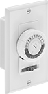
Outlet-Box-Mount Time and Day Activated Switches
 |
24-Hr. Timing Cycle |
Switches fit 1 gang outlet boxes. Program them to turn a device on and off at a set time and day. They’re often used with lamps and other small electrical loads.
24-Hr. Timing Cycle—24-hr. switches repeat the same program daily. Position trippers around the clock dial to set on and off times.
No. of Circuits Controlled | Switching Current @ Voltage | Max. On/Off Cycles, per day | Min. Set Time, min. | Timing Adjustment Style | Tripper Type | Switch Designation | For Outlet Box Designation | Wire Connection | Wire Lead Lg. | Certification | Each | |||
|---|---|---|---|---|---|---|---|---|---|---|---|---|---|---|
24-Hr. Timing Cycle—With On/Off/Timer Selector | ||||||||||||||
| 1 | 20 amp @ 120V AC | 24 | 30 | Tripper | Captive | SPST | 1 Gang | Wire Leads | 6" | UL Listed, C-UL Listed | 7367K4 | 000000 | ||
Enclosure Thermostats
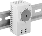 | 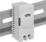 |
Adjustable Thermostat (12.6° F Temperature Difference) | Adjustable Thermostat (7° F Temperature Difference) |
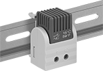 | |
Fixed Thermostat |
Control a single heating or cooling device in your enclosure to keep electronics at a safe operating temperature. Clip them on to a DIN rail and connect them to your heater, fan, or air conditioner. All these thermostats meet American, Canadian, or European safety standards.
Cooling—Cooling thermostats are normally open, so they’ll switch your fan or air conditioner on when the air in your enclosure reaches the temperature setting.
Heating—Heating thermostats are normally closed—when the air in your enclosure reaches the temperature setting, the thermostat will turn the heater off.
Adjustable Actuation Point—Adjustable thermostats let you set the temperature you need.
Fixed Actuation Point—Fixed thermostats have a fixed temperature setting to prevent tampering or accidental changes.
IP20 Enclosure Rating—They have an IP20 rating—to prevent shocks, fingers won’t fit inside.
UL 94 V-0—They also meet UL 94 V-0, so they self-extinguish within 10 seconds if they catch fire and won’t spread the fire by dripping.
Temperature Setting—These thermostats keep the air in your enclosure within a set range. Temperature setting is the high end of the range for both heating and cooling thermostats.
Temperature Difference—Temperature difference is the difference between the temperature when the thermostat turns your device on and when it turns off. For a heater thermostat with a temperature setting of 50° and an 18° temperature difference, the thermostat will switch your heater on when the temperature goes below 32° and off once the temperature reaches 50°. Thermostats with a lower temperature difference maintain a narrower range of temperatures, but they use more power because they switch on and off more frequently.
Temp. | Overall | ||||||||||||||
|---|---|---|---|---|---|---|---|---|---|---|---|---|---|---|---|
Setting | Difference | Tolerance | Voltage | Current, amp | For DIN Rail Ht., mm | Ht. | Wd. | Dp. | Enclosure Rating | Flammability Rating | Certification | Each | |||
Cooling | |||||||||||||||
Adjustable Actuation Point | |||||||||||||||
| 14° F to 122° F | 12.6° F | -7° F to 7° F | 120V AC, 240V AC | 16 | 35 | 2.4" | 1.3" | 1.6" | IP20 | UL 94 V-0 | C-UL Recognized Component, CE Marked, CSA Certified, UL Recognized Component, VDE Certified | 3941N13 | 000000 | ||
| 32° F to 140° F | 12.6° F | -7° F to 7° F | 120V AC, 240V AC | 16 | 35 | 2.4" | 1.3" | 1.6" | IP20 | UL 94 V-0 | C-UL Recognized Component, CE Marked, CSA Certified, UL Recognized Component, VDE Certified | 19155K16 | 00000 | ||
| 32° F to 140° F | 7° F | -5.4° F to 5.4° F | 120V AC, 240V AC, 24V DC to 75V DC | 16 | 35 | 2 13/16" | 1 5/16" | 1 11/16" | IP20 | UL 94 V-0 | CE Marked | 3941N14 | 00000 | ||
Fixed Actuation Point | |||||||||||||||
| 95° F, 35° C | 18° F, 10° C | -11° F to 11° F/-6° C to 6° C | 120V AC, 240V AC, 24V DC to 75V DC | 16 | 35 | 1 7/8" | 1 5/16" | 1 5/16" | IP20 | UL 94 V-0 | C-UL Recognized Component, CE Marked, UL Recognized Component, VDE Certified | 3941N21 | 00000 | ||
| 122° F, 50° C | 18° F, 10° C | -11° F to 11° F/-6° C to 6° C | 120V AC, 240V AC, 24V DC to 75V DC | 16 | 35 | 1 7/8" | 1 5/16" | 1 5/16" | IP20 | UL 94 V-0 | C-UL Recognized Component, CE Marked, UL Recognized Component, VDE Certified | 3941N18 | 00000 | ||
| 140° F, 60° C | 18° F, 10° C | -12.6° F to 12.6° F/-7° C to 7° C | 120V AC, 240V AC, 24V DC to 75V DC | 16 | 35 | 1 7/8" | 1 5/16" | 1 5/16" | IP20 | UL 94 V-0 | C-UL Recognized Component, CE Marked, UL Recognized Component, VDE Certified | 3941N19 | 00000 | ||
Heating | |||||||||||||||
Adjustable Actuation Point | |||||||||||||||
| 14° F to 122° F | 12.6° F | -7° F to 7° F | 120V AC, 240V AC | 16 | 35 | 2.4" | 1.3" | 1.6" | IP20 | UL 94 V-0 | C-UL Recognized Component, CE Marked, CSA Certified, UL Recognized Component, VDE Certified | 3941N11 | 00000 | ||
| 32° F to 140° F | 12.6° F | -7° F to 7° F | 120V AC, 240V AC | 16 | 35 | 2.4" | 1.3" | 1.6" | IP20 | UL 94 V-0 | C-UL Recognized Component, CE Marked, CSA Certified, UL Recognized Component, VDE Certified | 1365K6 | 00000 | ||
| 32° F to 140° F | 7° F | -5.4° F to 5.4° F | 120V AC, 240V AC, 24V DC to 75V DC | 16 | 35 | 2 13/16" | 1 5/16" | 1 11/16" | IP20 | UL 94 V-0 | CE Marked | 3941N12 | 00000 | ||
Fixed Actuation Point | |||||||||||||||
| 50° F, 10° C | 18° F, 10° C | -9° F to 9° F/-5° C to 5° C | 120V AC, 240V AC, 24V DC to 75V DC | 16 | 35 | 1 7/8" | 1 5/16" | 1 5/16" | IP20 | UL 94 V-0 | C-UL Recognized Component, CE Marked, UL Recognized Component, VDE Certified | 3941N17 | 00000 | ||
| 59° F, 15° C | 18° F, 10° C | -9° F to 9° F/-5° C to 5° C | 120V AC, 240V AC, 24V DC to 75V DC | 16 | 35 | 1 7/8" | 1 5/16" | 1 5/16" | IP20 | UL 94 V-0 | C-UL Recognized Component, CE Marked, UL Recognized Component, VDE Certified | 3941N15 | 00000 | ||
| 77° F, 25° C | 18° F, 10° C | -9° F to 9° F/-5° C to 5° C | 120V AC, 240V AC, 24V DC to 75V DC | 16 | 35 | 1 7/8" | 1 5/16" | 1 5/16" | IP20 | UL 94 V-0 | C-UL Recognized Component, CE Marked, UL Recognized Component, VDE Certified | 3941N16 | 00000 | ||
Snap-Acting Thermostats
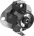 |
Also known as snap discs, these thermostats switch on cooling systems or switch off heating systems when equipment gets too hot. Each thermostat has five temperature options for switch activation; choose the one that best suits your application.
Unlike heat-actuated switches, these thermostats reset automatically, saving you the effort of replacing a melted fusible link. To calculate their reset temperature, subtract their differential temperature from the temperature you set them at. For example, a thermostat set at 100° F with a 20° F differential will reset at 80° F.
Close Switch at Temperature Setting—Normally closed thermostats are also known as high-limit thermostats—they turn off at a set temperature. They’re often used with electric water heaters, stoves, and furnaces.
Open Switch at Temperature Setting—Normally open thermostats are also known as low-limit thermostats—they turn on at a set temperature. They’re good for use with fans and blowers.
Overall | |||||||||||||||||
|---|---|---|---|---|---|---|---|---|---|---|---|---|---|---|---|---|---|
Temp. Setting, ° F | Max. Temp. Differential, ° F | Switch Designation | Switch Starting Position | Voltage, V AC | Current, amp | Wire Connection | Terminal Size | Face Dia. | Ht. | Wd. | Dp. | Hole Diameter (No. of) | Mounting Fasteners Included | Each | |||
Close Switch at Temperature Setting | |||||||||||||||||
| 90, 100, 110, 120, 130 | 20 | SPST | 1 Off | 120, 240 | 25 | Quick-Disconnect Terminal | 1/4" | 3/4" | 1 3/4" | 2" | 1 3/8" | 3/16" (2) | No | 8624N11 | 000000 | ||
| 140, 150, 160, 170, 180 | 20 | SPST | 1 Off | 120, 240 | 25 | Quick-Disconnect Terminal | 1/4" | 3/4" | 1 3/4" | 2" | 1 3/8" | 3/16" (2) | No | 8624N12 | 00000 | ||
Open Switch at Temperature Setting | |||||||||||||||||
| 135, 145, 155, 165, 175 | 20 | SPST | 1 On | 120, 240 | 25 | Quick-Disconnect Terminal | 1/4" | 3/4" | 1 3/4" | 2" | 1 3/8" | 3/16" (2) | No | 8624N16 | 00000 | ||
| 135, 145, 155, 165, 175 | 40 | SPST | 1 On | 120, 240 | 25 | Quick-Disconnect Terminal | 1/4" | 3/4" | 1 3/4" | 2" | 1 3/8" | 3/16" (2) | No | 8624N13 | 00000 | ||
| 175, 185, 195, 205, 215 | 40 | SPST | 1 On | 120, 240 | 25 | Quick-Disconnect Terminal | 1/4" | 3/4" | 1 3/4" | 2" | 1 3/8" | 3/16" (2) | No | 8624N14 | 00000 | ||
| 210, 220, 230, 240, 250 | 40 | SPST | 1 On | 120, 240 | 25 | Quick-Disconnect Terminal | 1/4" | 3/4" | 1 3/4" | 2" | 1 3/8" | 3/16" (2) | No | 8624N15 | 00000 | ||
| 250, 260, 270, 280, 290 | 40 | SPST | 1 On | 120, 240 | 25 | Quick-Disconnect Terminal | 1/4" | 3/4" | 1 3/4" | 2" | 1 3/8" | 3/16" (2) | No | 8624N17 | 00000 | ||
Electronic Flow Switches
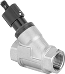 |
When these switches reach a set flow rate, they send digital signals to your programmable logic controller (PLC) to activate automated controls or alarms. Use the adjustment screw to select their set point. As flowing liquid pushes an internal piston, the switch reads the position of the piston to measure the flow. When the piston passes the set point, the switch actuates. They must be mounted horizontally to function correctly. IP rated, they withstand dust, washdowns, and temporary submersion.
These switches are calibrated with and measure water accurately. They can also be used with other liquids by applying your liquid’s specific-gravity conversion factor to calculate the new set point.
Pipe Connections | Flow Set Point, gpm | Max. Pressure @ Temp. | Temp. Range, ° F | Voltage, V DC | Max. Switching Current @ Voltage | End-to-End Lg. | Enclosure Rating | Certification | Each | |||
|---|---|---|---|---|---|---|---|---|---|---|---|---|
Aluminum/Brass/Plastic Body with Threaded Nickel-Plated Brass Fittings | ||||||||||||
1 PNP Output Signal | ||||||||||||
| 3/4 NPT Female | 0.26 to 6.6 | 360 psi @ 70° F | 32 to 185 | 30 | 100 mA @ 30V DC | 3" | IP65, IP67 | C-UL Listed UL Listed CE Marked | 4546N11 | 0000000 | ||
| 1 NPT Female | 1.32 to 26.4 | 360 psi @ 70° F | 32 to 185 | 30 | 100 mA @ 30V DC | 3 5/8" | IP65, IP67 | C-UL Listed UL Listed CE Marked | 4546N12 | 000000 | ||
Photoelectric Sensors with Relay Output
With Screw Terminals
 |
Direct Sensing—Direct sensing sensors detect objects when light reflects back from the object. The transmitter and receiver are in the same housing, so they fit in confined spaces.
Receiver Sensor—Receiver sensors detect objects when an object breaks the light beam between the transmitter and receiver (both included). They have a longer sensing distance than direct-sensing and reflector sensors.
Reflector Sensor—Reflector sensors detect an object when it passes between the sensor and the reflector, interrupting the beam. They have a longer sensing distance than direct-sensing sensors.
IP66 Enclosure Rating—IP66 rated sensors protect against washdowns.
Sensors | Reflectors | ||||||||||||||||||||
|---|---|---|---|---|---|---|---|---|---|---|---|---|---|---|---|---|---|---|---|---|---|
Reflector | |||||||||||||||||||||
Light Beam Switch Operation | Max. Sensing Distance | Switch Designation | Switching Current @ Voltage | Input Voltage | Lg. | Ht. | Wd. | Includes | Features | Housing Material | Ht. | Wd. | Temp. Range, ° F | Environment | Certification | Each | Each | ||||
Direct Sensing Sensor with Infrared LED Light Beam (IP66) | |||||||||||||||||||||
| On When Object Absent, On When Object Present | 39" | SPST | 3 amp @ 250V AC/30V DC | 24V AC to 240V AC/24V DC to 240V DC | 2 3/4" | 2 11/16" | 1" | — | Relay | Plastic | — | — | -10 to 130 | Washdown Dusty Wet | CE Marked | 9231K11 | 0000000 | ——— | 0 | ||
Receiver Sensor with Visible LED Light Beam (IP66) | |||||||||||||||||||||
| On When Object Absent, On When Object Present | 65.5 ft. | SPST | 3 amp @ 250V AC/30V DC | 24V AC to 240V AC/24V DC to 240V DC | 2 3/4" | 2 11/16" | 1" | — | Relay | Plastic | — | — | -10 to 130 | Washdown Dusty Wet | CE Marked | 9231K13 | 000000 | ——— | 0 | ||
Reflector Sensor with Visible LED Light Beam (IP66) | |||||||||||||||||||||
| On When Object Absent, On When Object Present | 23 ft. | SPST | 3 amp @ 250V AC/30V DC | 24V AC to 240V AC/24V DC to 240V DC | 2 3/4" | 2 11/16" | 1" | Reflector | Relay | Plastic | 2 3/8" | 1 5/8" | -10 to 130 | Washdown Dusty Wet | CE Marked | 9231K12 | 000000 | 9231K31 | 000000 | ||
Fixed-Set-Point Flow Switches
 |  |
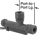
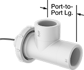
Style A | Style B |
 |  |
Style D | Style E |
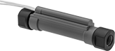
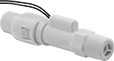
Since they come factory set to a specific set point, these switches are easier to install than adjustable flow switches. As flowing liquid pushes an internal piston, the switch reads the position of the piston to measure the flow. When the piston passes the set point, the switch actuates. They’re accurate in any mounting position.
These switches are calibrated with and measure water accurately. They can also be used with other liquids by applying your liquid’s specific-gravity conversion factor to calculate the new set point.
Choose a fitting material that is compatible with the liquid you intend to run through your line.
Straight
| |
Style A | Style B |
Polypropylene Fitting—Polypropylene and PPS fittings work with a wide range of chemicals. However, they can crack from impact or when overtightened.
SPST—SPST (single pole, single throw) switches turn one device from off to on (normally open).
Style | Pipe Size | Thread Type | Gender | Set Point, gpm | Approx. Difference Between Set Point and Reset Point, gpm | Max. Pressure @ Temp. | Temp. Range, ° F | Max. Switching Current @ Voltage | End-to-End Lg. | Mounting Position | Each | |||
|---|---|---|---|---|---|---|---|---|---|---|---|---|---|---|
Polypropylene Body with Polypropylene Fittings | ||||||||||||||
SPST | ||||||||||||||
| A | 1/4 | NPT | Female | 0.1 | 0.1 | 200 psi @ 70° F | 33 to 194 | 500 mA @ 300V AC 700 mA @ 350V DC | 4 7/8" | Any Angle | 2371K41 | 000000 | ||
| A | 1/4 | NPT | Female | 0.25 | 0.25 | 200 psi @ 70° F | 33 to 194 | 500 mA @ 300V AC 700 mA @ 350V DC | 4 7/8" | Any Angle | 2371K42 | 00000 | ||
| A | 1/4 | NPT | Female | 0.5 | 0.5 | 200 psi @ 70° F | 33 to 194 | 500 mA @ 300V AC 700 mA @ 350V DC | 4 7/8" | Any Angle | 2371K43 | 00000 | ||
| A | 1/4 | NPT | Female | 0.75 | 0.75 | 200 psi @ 70° F | 33 to 194 | 500 mA @ 300V AC 700 mA @ 350V DC | 4 7/8" | Any Angle | 2371K44 | 00000 | ||
| A | 1/4 | NPT | Female | 1 | 1 | 200 psi @ 70° F | 33 to 194 | 500 mA @ 300V AC 700 mA @ 350V DC | 4 7/8" | Any Angle | 2371K45 | 00000 | ||
| B | 3/8 | NPT | Male | 0.25 | 0.05 | 125 psi @ 70° F | 33 to 212 | 400 mA @ 30V AC 170 mA @ 120V AC 80 mA @ 240V AC 300 mA @ 30V DC 130 mA @ 120V DC 60 mA @ 240V DC | 4" | Any Angle | 42015K21 | 00000 | ||
| B | 3/8 | NPT | Male | 0.5 | 0.1 | 125 psi @ 70° F | 33 to 212 | 400 mA @ 30V AC 170 mA @ 120V AC 80 mA @ 240V AC 300 mA @ 30V DC 130 mA @ 120V DC 60 mA @ 240V DC | 4" | Any Angle | 42015K22 | 00000 | ||
| B | 3/8 | NPT | Male | 1 | 0.2 | 125 psi @ 70° F | 33 to 212 | 400 mA @ 30V AC 170 mA @ 120V AC 80 mA @ 240V AC 300 mA @ 30V DC 130 mA @ 120V DC 60 mA @ 240V DC | 4" | Any Angle | 42015K23 | 00000 | ||
| B | 3/8 | NPT | Male | 1.5 | 0.3 | 125 psi @ 70° F | 33 to 212 | 400 mA @ 30V AC 170 mA @ 120V AC 80 mA @ 240V AC 300 mA @ 30V DC 130 mA @ 120V DC 60 mA @ 240V DC | 4" | Any Angle | 42015K24 | 00000 | ||
| B | 3/8 | NPT | Male | 2 | 0.4 | 125 psi @ 70° F | 33 to 212 | 400 mA @ 30V AC 170 mA @ 120V AC 80 mA @ 240V AC 300 mA @ 30V DC 130 mA @ 120V DC 60 mA @ 240V DC | 4" | Any Angle | 42015K25 | 00000 | ||
90° Elbow
| |
Style D | Style E |
Style | Pipe Size | Thread Type | Gender | Set Point, gpm | Approx. Difference Between Set Point and Reset Point, gpm | Max. Pressure @ Temp. | Temp. Range, ° F | Max. Switching Current @ Voltage | Mounting Position | Each | |||
|---|---|---|---|---|---|---|---|---|---|---|---|---|---|
Polypropylene Body with Polypropylene Fittings | |||||||||||||
SPST | |||||||||||||
| D | 1/4 | NPT | Female | 0.042 | 0.006 | 200 psi @ 70° F | 33 to 194 | 500 mA @ 300V AC 700 mA @ 350V DC | Any Angle | 4553N15 | 000000 | ||
| D | 1/4 | NPT | Female | 0.1 | 0.1 | 200 psi @ 70° F | 33 to 194 | 500 mA @ 300V AC 700 mA @ 350V DC | Any Angle | 2371K21 | 00000 | ||
| D | 1/4 | NPT | Female | 0.25 | 0.25 | 200 psi @ 70° F | 33 to 194 | 500 mA @ 300V AC 700 mA @ 350V DC | Any Angle | 2371K22 | 00000 | ||
| D | 1/4 | NPT | Female | 0.5 | 0.5 | 200 psi @ 70° F | 33 to 194 | 500 mA @ 300V AC 700 mA @ 350V DC | Any Angle | 2371K23 | 00000 | ||
| D | 1/4 | NPT | Female | 0.75 | 0.75 | 200 psi @ 70° F | 33 to 194 | 500 mA @ 300V AC 700 mA @ 350V DC | Any Angle | 2371K24 | 00000 | ||
| D | 1/4 | NPT | Female | 1 | 1 | 200 psi @ 70° F | 33 to 194 | 500 mA @ 300V AC 700 mA @ 350V DC | Any Angle | 2371K25 | 00000 | ||
| E | 3/4 | NPT | Female | 0.25 | 0.05 | 100 psi @ 70° F | 0 to 212 | 400 mA @ 30V AC 170 mA @ 120V AC 80 mA @ 240V AC 300 mA @ 30V DC 130 mA @ 120V DC 60 mA @ 240V DC | Any Angle | 4553N13 | 000000 | ||
| E | 3/4 | NPT | Female | 0.5 | 0.1 | 100 psi @ 70° F | 0 to 212 | 400 mA @ 30V AC 170 mA @ 120V AC 80 mA @ 240V AC 300 mA @ 30V DC 130 mA @ 120V DC 60 mA @ 240V DC | Any Angle | 42015K6 | 000000 | ||
| E | 3/4 | NPT | Female | 1 | 0.2 | 100 psi @ 70° F | 0 to 212 | 400 mA @ 30V AC 170 mA @ 120V AC 80 mA @ 240V AC 300 mA @ 30V DC 130 mA @ 120V DC 60 mA @ 240V DC | Any Angle | 4553N14 | 000000 | ||
Set-to-the-Minute High-Current Time and Day Activated Switches
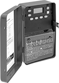 |
For precise control of high-current equipment such as landscape lighting, pumps, and heaters, these switches schedule on/off times to the exact minute. A backup battery or capacitor maintains the program during a power outage.
7-Day Timing Cycle—Seven-day switches can perform a different program each day of the week. They have a day skipper that can suspend operation for one to six days.
2 Circuits Controlled—Two-circuit switches can apply a different program to each circuit.
Mounting | ||||||||||||||||||||
|---|---|---|---|---|---|---|---|---|---|---|---|---|---|---|---|---|---|---|---|---|
No. of Circuits Controlled | Switching Current @ Voltage | Input Voltage, V AC | Max. On/Off Cycles, per day | Min. Set Time, min. | Timing Adjustment Style | Housing Material | Switch Designation | Ht. | Wd. | Dp. | Fasteners Included | Hole Dia. | Knockout Trade Size | Wire Connection | Environment | Certification | Each | |||
7 day—With Battery Backup, Lockout, Day Skipper | ||||||||||||||||||||
| 2 | 30 amp @ 240V AC | 120/208/240/277 | 28 | 1 | Push Button | Steel | SPST, DPST | 7 3/4" | 5" | 3" | No | 0.16" | 1/2, 3/4 | Screw Terminal | Indoor Only | UL Listed, CSA Certified | 7459K89 | 0000000 | ||
24-Hr. Timing Cycle—With Capacitor Backup, Lockout | ||||||||||||||||||||
| 1 | 30 amp @ 240V AC | 120/208/240/277 | 48 | 1 | Push Button | Steel | SPST | 7 7/8" | 5 1/8" | 3 7/16" | No | 3/16" | 1/2, 3/4 | Screw Terminal | Indoor Only | UL Listed, CSA Certified | 7459K81 | 000000 | ||
| 2 | 30 amp @ 240V AC | 120/208/240/277 | 48 | 1 | Push Button | Steel | SPST, DPST | 7 7/8" | 5 1/8" | 3 7/16" | No | 3/16" | 1/2, 3/4 | Screw Terminal | Indoor Only | UL Listed, CSA Certified | 7459K82 | 000000 | ||
7-Day Timing Cycle—With Capacitor Backup, Day Skipper, Lockout | ||||||||||||||||||||
| 1 | 30 amp @ 240V AC | 120/208/240/277 | 48 | 1 | Push Button | Steel | SPST | 7 7/8" | 5 1/8" | 3 7/16" | No | 3/16" | 1/2, 3/4 | Screw Terminal | Indoor Only | UL Listed, CSA Certified | 7459K83 | 000000 | ||
Enclosure Thermostats for Multiple Devices
For Heating and Cooling Thermostats with Two Actuation Points
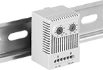 | 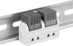 |
Adjustable Thermostat with Two Actuation Points | Fixed Thermostat |
Heating Temperature | Cooling Temperature | Overall | ||||||||||||||
|---|---|---|---|---|---|---|---|---|---|---|---|---|---|---|---|---|
Setting | Difference | Tolerance | Setting | Difference | Tolerance | Voltage | Ht. | Wd. | Dp. | Enclosure Rating | Flammability Rating | Certification | Each | |||
Adjustable Actuation Point | ||||||||||||||||
| 14° F to 122° F | 12.6° F | -7° F to 7° F | 68° F to 176° F | 12.6° F | -7° F to 7° F | 120V AC, 240V AC | 2 5/8" | 2" | 1 13/16" | IP20 | UL 94 V-0 | C-UL Recognized Component, CE Marked, CSA Certified, UL Recognized Component, VDE Certified | 6967N12 | 000000 | ||
| 32° F to 140° F | 12.6° F | -7° F to 7° F | 32° F to 140° F | 12.6° F | -7° F to 7° F | 120V AC, 240V AC | 2 5/8" | 2" | 1 13/16" | IP20 | UL 94 V-0 | C-UL Recognized Component, CE Marked, CSA Certified, UL Recognized Component, VDE Certified | 6967N11 | 00000 | ||
Fixed Actuation Point | ||||||||||||||||
| 59° F, 15° C | 18° F, 10° C | -9° F to 9° F, -5° C to 5° C | 95° F, 35° C | 18° F, 10° C | -12.6° F to 12.6° F, -7° C to 7° C | 120V AC, 240V AC, 24V DC to 75V DC | 1 7/8" | 2 1/2" | 1 5/16" | IP20 | UL 94 V-0 | C-UL Recognized Component, CE Marked, UL Recognized Component, VDE Certified | 6967N16 | 00000 | ||
| 59° F, 15° C | 18° F, 10° C | -9° F to 9° F, -5° C to 5° C | 122° F, 50° C | 18° F, 10° C | -12.6° F to 12.6° F, -7° C to 7° C | 120V AC, 240V AC, 24V DC to 75V DC | 1 7/8" | 2 1/2" | 1 5/16" | IP20 | UL 94 V-0 | C-UL Recognized Component, CE Marked, UL Recognized Component, VDE Certified | 6967N14 | 00000 | ||
| 77° F, 25° C | 18° F, 10° C | -9° F to 9° F, -5° C to 5° C | 122° F, 50° C | 18° F, 10° C | -12.6° F to 12.6° F, -7° C to 7° C | 120V AC, 240V AC, 24V DC to 75V DC | 1 7/8" | 2 1/2" | 1 5/16" | IP20 | UL 94 V-0 | C-UL Recognized Component, CE Marked, UL Recognized Component, VDE Certified | 6967N17 | 00000 | ||
For Cooling Thermostats with Two Actuation Points
|
Adjustable Thermostat with Two Actuation Points |
|
Fixed Thermostat |
Cooling thermostats regulate two cooling devices, such as a fan and an air conditioner, for two-stage cooling. Use only one device for cooling in mild temperatures or both for extreme heat. These thermostats switch your equipment on when the enclosure is hotter than the temperature setting. Once the temperature is reduced by the temperature difference, it will switch off. For example, a thermostat set at 77° F for a fan and 140° F for an air conditioner will power both devices when the enclosure is over 140° F. With a temperature difference of 18° F, the air conditioner will switch off when the temperature goes below 122° F. The fan will run until the temperature reaches 59° F, and switch back on if it heats up to 77° F or hotter.
Adjustable Actuation Point—Adjustable thermostats allow you to set custom temperatures.
Fixed Actuation Point—Fixed thermostats prevent tampering and accidental changes.
IP20 Enclosure Rating—All thermostats meet IP20, which means they’re designed so fingers can’t fit inside and get shocked.
UL 94 V-0—They also meet UL 94 V-0, so they self-extinguish within 10 seconds if they catch fire and won’t spread the fire by dripping.
Certification—Thermostats that are CE marked or VDE certified meet European safety standards. UL Recognized Component and C-UL Recognized Component thermostats also meet American and Canadian safety standards.
Cooling Temperature | Cooling Temperature Second Actuation Point | Overall | ||||||||||||||
|---|---|---|---|---|---|---|---|---|---|---|---|---|---|---|---|---|
Setting | Difference | Tolerance | Setting | Difference | Tolerance | Voltage | Ht. | Wd. | Dp. | Enclosure Rating | Flammability Rating | Certification | Each | |||
Adjustable Actuation Point | ||||||||||||||||
| 32° F to 140° F | 12.6° F | -7° F to 7° F | 32° F to 140° F | 12.6° F | -7° F to 7° F | 120V AC, 240V AC | 2 5/8" | 2" | 1 13/16" | IP20 | UL 94 V-0 | C-UL Recognized Component, CE Marked, CSA Certified, UL Recognized Component, VDE Certified | 6967N13 | 000000 | ||
Fixed Actuation Point | ||||||||||||||||
| 122° F, 50° C | 18° F, 10° C | -12.6° F to 12.6° F, -7° C to 7° C | 140° F, 60° C | 18° F, 10° C | -12.6° F to 12.6° F, -7° C to 7° C | 120V AC, 240V AC, 24V DC to 75V DC | 1 7/8" | 2 1/2" | 1 5/16" | IP20 | UL 94 V-0 | C-UL Recognized Component, CE Marked, UL Recognized Component, VDE Certified | 6967N18 | 00000 | ||
Fixed-Set-Point Flow Switches for Drinking Water
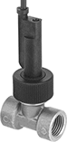 |
Factory set to activate equipment when your drinking water system reaches a fixed level, these flow switches are easier to install than adjustable flow switches. They meet NSF/ANSI 61, so they're safe to use with drinking water. They actuate when your system’s flowing water pushes their paddle into a set position. These switches are single pole, single throw (SPST) and turn one device from off to on. IP rated, they seal out dust and can be lightly rinsed. They're accurate in any mounting position.
These flow switches are calibrated with water. You can use them with other liquids, but they may not measure accurately if the liquid’s viscosity differs from water.
Pipe Connections | Set Point, gpm | Max. Pressure @ Temp. | Temp. Range, ° F | Voltage | Max. Switching Current @ Voltage | End-to-End Lg. | Enclosure Rating | Certification | Food Industry Std. | Each | |||
|---|---|---|---|---|---|---|---|---|---|---|---|---|---|
Noryl Body with Threaded Brass Fittings | |||||||||||||
| 1/2 NPT Female | 0.6 | 145 psi @ 70° F | -4 to 212 | 230V AC/48V DC | 1 amp @ 230V AC 1 amp @ 48V DC | 2" | IP65 | CE Marked | NSF/ANSI 61 | 4646N11 | 0000000 | ||
High-Current Time and Day Activated Switches
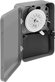 |
Control equipment with high currents such as landscape lighting, pumps, and heaters. Program these switches to turn a device on and off at a set time and day. Position trippers around the clock dial to set on and off times.
24-Hr. Timing Cycle—24-hr. switches repeat the same program daily.
Day Skipper—Switches with a day skipper can be programmed to skip operation for one to six days.
Trippers—Additional trippers (sold separately) are sold in pairs that include one “on” tripper and one “off” tripper.
Switches | Trippers | ||||||||||||||||||
|---|---|---|---|---|---|---|---|---|---|---|---|---|---|---|---|---|---|---|---|
No. of Circuits Controlled | Switching Current @ Voltage | Input Voltage, V AC | Max. On/Off Cycles, per day | Min. Set Time, hr. | Tripper Type | No. of Trippers | Switch Designation | Ht. | Wd. | Dp. | Wire Connection | Environment | Each | No. of Trippers Included | Pkg. | ||||
24-Hr. Timing Cycle | |||||||||||||||||||
| 1 | 40 amp @ 240V AC | 120 | 12 | 1 | Removable | 2 | SPST | 7 3/4" | 5" | 3" | Screw Terminal | Indoor Only | 7037K11 | 000000 | 1 Pair | 7037K32 | 00000 | ||
24-Hr. Timing Cycle with Day Skipper and Three Skip Screws | |||||||||||||||||||
| 1 | 40 amp @ 240V AC | 120 | 10 | 1 | Removable | 2 | SPST | 7 3/4" | 5" | 3" | Screw Terminal | Indoor Only | 7037K17 | 000000 | 1 Pair | 7037K42 | 0000 | ||
Line-Voltage Thermostats
 |
For Heaters |
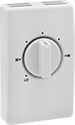
Regulate line-voltage HVAC systems.
For Heaters—Thermostats for heaters mount to a surface-mount outlet box.
Cannot Be Sold To—Energy efficiency requirements restrict sales to the listed jurisdictions/areas.
Overall | ||||||||||||||||
|---|---|---|---|---|---|---|---|---|---|---|---|---|---|---|---|---|
Voltage, V AC | Current, amp | Temp. Setting, ° F | Switch Designation | Electrical Connection Type | Ht. | Wd. | Dp. | For Use Outdoors | Mounting Fasteners Included | Display Type | Certification | Cannot Be Sold To | Each | |||
For Heaters | ||||||||||||||||
Dial Control | ||||||||||||||||
| 120 to 277 | 22 | 50 to 90 | SPST | Hardwire | 4 1/2" | 2 3/4" | 1 1/2" | No | No | Analog | ETL Listed | Colorado | 17395K93 | 000000 | ||
Outdoor Set-to-the-Minute High-Current Time and Day Activated Switches
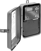 |
Rated NEMA 3R, these rain-tight switches protect against falling liquids and light splashing. More precise than other time and day switches, they program on/off times for equipment down to the exact minute. They control equipment with high currents, such as landscape lighting, pumps, and heaters. A backup battery maintains the program during a power outage.
24-Hr. Timing Cycle—24-hr. switches repeat the same program daily.
Mounting | ||||||||||||||||||||
|---|---|---|---|---|---|---|---|---|---|---|---|---|---|---|---|---|---|---|---|---|
No. of Circuits Controlled | Switching Current @ Voltage | Input Voltage, V AC | Max. On/Off Cycles, per day | Min. Set Time, min. | Timing Adjustment Style | Housing Material | Switch Designation | Ht. | Wd. | Dp. | Fasteners Included | Hole Dia. | Knockout Trade Size | Wire Connection | Environment | Certification | Each | |||
24-Hr. Timing Cycle—With Battery Backup, Lockout | ||||||||||||||||||||
| 1 | 30 amp @ 240V AC | 120/208/240/277 | 20 | 1 | Push Button | Polycarbonate | SPST | 8 3/8" | 5" | 3 1/8" | No | 0.26" | 1/2, 3/4 | Screw Terminal | Outdoor, Wet | UL Listed | 7459K65 | 0000000 | ||
Fixed-Set-Point High-Pressure Flow Switches
Straight
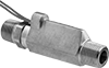 |
SPST—SPST (single pole, single throw) switches turn one device from off to on (normally open).
Pipe Connections | Set Point, gpm | Approx. Difference Between Set Point and Reset Point, gpm | Max. Pressure @ Temp. | Temp. Range, ° F | Max. Switching Current @ Voltage | End-to-End Lg. | Each | |||
|---|---|---|---|---|---|---|---|---|---|---|
SPST | ||||||||||
Brass Body with Brass Fittings | ||||||||||
| 3/8 NPT Male | 0.25 | 0.05 | 1,500 psi @ 70° F | -20 to 275 | 0.4 amp @ 30V AC 0.17 amp @ 120V AC 0.08 amp @ 240V AC 0.3 amp @ 30V DC 0.13 amp @ 120V DC 0.06 amp @ 240V DC | 3 7/16" | 4960K51 | 0000000 | ||
| 3/8 NPT Male | 0.5 | 0.1 | 1,500 psi @ 70° F | -20 to 275 | 0.4 amp @ 30V AC 0.17 amp @ 120V AC 0.08 amp @ 240V AC 0.3 amp @ 30V DC 0.13 amp @ 120V DC 0.06 amp @ 240V DC | 3 7/16" | 4960K52 | 000000 | ||
| 3/8 NPT Male | 1 | 0.2 | 1,500 psi @ 70° F | -20 to 275 | 0.4 amp @ 30V AC 0.17 amp @ 120V AC 0.08 amp @ 240V AC 0.3 amp @ 30V DC 0.13 amp @ 120V DC 0.06 amp @ 240V DC | 3 7/16" | 4960K53 | 000000 | ||
| 3/8 NPT Male | 1.5 | 0.3 | 1,500 psi @ 70° F | -20 to 275 | 0.4 amp @ 30V AC 0.17 amp @ 120V AC 0.08 amp @ 240V AC 0.3 amp @ 30V DC 0.13 amp @ 120V DC 0.06 amp @ 240V DC | 3 7/16" | 4960K54 | 000000 | ||
| 3/8 NPT Male | 2 | 0.4 | 1,500 psi @ 70° F | -20 to 275 | 0.4 amp @ 30V AC 0.17 amp @ 120V AC 0.08 amp @ 240V AC 0.3 amp @ 30V DC 0.13 amp @ 120V DC 0.06 amp @ 240V DC | 3 7/16" | 4960K55 | 000000 | ||
| 1/2 NPT Male | 0.25 | 0.05 | 1,500 psi @ 70° F | -20 to 275 | 0.4 amp @ 30V AC 0.17 amp @ 120V AC 0.08 amp @ 240V AC 0.3 amp @ 30V DC 0.13 amp @ 120V DC 0.06 amp @ 240V DC | 4" | 4960K61 | 000000 | ||
| 1/2 NPT Male | 0.5 | 0.1 | 1,500 psi @ 70° F | -20 to 275 | 0.4 amp @ 30V AC 0.17 amp @ 120V AC 0.08 amp @ 240V AC 0.3 amp @ 30V DC 0.13 amp @ 120V DC 0.06 amp @ 240V DC | 4" | 4960K62 | 000000 | ||
| 1/2 NPT Male | 1 | 0.2 | 1,500 psi @ 70° F | -20 to 275 | 0.4 amp @ 30V AC 0.17 amp @ 120V AC 0.08 amp @ 240V AC 0.3 amp @ 30V DC 0.13 amp @ 120V DC 0.06 amp @ 240V DC | 4" | 4960K63 | 000000 | ||
| 1/2 NPT Male | 1.5 | 0.3 | 1,500 psi @ 70° F | -20 to 275 | 0.4 amp @ 30V AC 0.17 amp @ 120V AC 0.08 amp @ 240V AC 0.3 amp @ 30V DC 0.13 amp @ 120V DC 0.06 amp @ 240V DC | 4" | 4960K64 | 000000 | ||
| 1/2 NPT Male | 2 | 0.4 | 1,500 psi @ 70° F | -20 to 275 | 0.4 amp @ 30V AC 0.17 amp @ 120V AC 0.08 amp @ 240V AC 0.3 amp @ 30V DC 0.13 amp @ 120V DC 0.06 amp @ 240V DC | 4" | 4960K65 | 000000 | ||
316 Stainless Steel Body with 316 Stainless Steel Fittings | ||||||||||
| 3/8 NPT Male | 0.25 | 0.05 | 1,500 psi @ 70° F | -20 to 275 | 0.4 amp @ 30V AC 0.17 amp @ 120V AC 0.08 amp @ 240V AC 0.3 amp @ 30V DC 0.13 amp @ 120V DC 0.06 amp @ 240V DC | 3 7/16" | 4960K71 | 000000 | ||
| 3/8 NPT Male | 0.5 | 0.1 | 1,500 psi @ 70° F | -20 to 275 | 0.4 amp @ 30V AC 0.17 amp @ 120V AC 0.08 amp @ 240V AC 0.3 amp @ 30V DC 0.13 amp @ 120V DC 0.06 amp @ 240V DC | 3 7/16" | 4960K72 | 000000 | ||
| 3/8 NPT Male | 2 | 0.4 | 1,500 psi @ 70° F | -20 to 275 | 0.4 amp @ 30V AC 0.17 amp @ 120V AC 0.08 amp @ 240V AC 0.3 amp @ 30V DC 0.13 amp @ 120V DC 0.06 amp @ 240V DC | 3 7/16" | 4960K75 | 000000 | ||
Plug-In Line-Voltage Thermostats
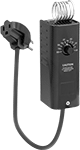 |
Plug in the thermostat, then plug your line-voltage heater into the socket on the thermostat's plug. Use the included metal hanger for mounting.
Electrical | Overall | |||||||||||||||||
|---|---|---|---|---|---|---|---|---|---|---|---|---|---|---|---|---|---|---|
Voltage, V AC | Current, amp | Temp. Setting, ° F | Switch Designation | Cord Lg., ft. | Electrical Connection Type | Connection | No. of Blades | Ht. | Wd. | Dp. | For Use Outdoors | Mounting Fasteners Included | Display Type | Certification | Each | |||
For Heaters | ||||||||||||||||||
Dial Control | ||||||||||||||||||
| 120 | 13 | 40 to 90 | SPST | 6 | Plug In | Straight Blade | 3 | 5 1/2" | 2 1/8" | 2 5/8" | No | No | Analog | UL Listed | 1940K8 | 0000000 | ||
Programmable Line-Voltage Thermostats
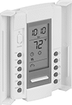 |
Set these thermostats to adjust the temperature at certain times each day. They regulate heaters that use direct electrical power, such as baseboard and wall heaters.
Cannot Be Sold To—Energy efficiency requirements restrict sales to the listed jurisdictions/areas.
For System | Overall | |||||||||||||||||
|---|---|---|---|---|---|---|---|---|---|---|---|---|---|---|---|---|---|---|
Type | Efficiency | Program Function | Voltage, V AC | Current, amp | Temp. Setting, ° F | Switch Designation | Electrical Connection Type | Ht. | Wd. | Dp. | For Use Outdoors | Mounting Fasteners Included | Display Type | Cannot Be Sold To | Each | |||
For Heaters | ||||||||||||||||||
Push-Button Control | ||||||||||||||||||
| Electric | Single Stage | Daily | 120 | 16 | 40 to 86 | SPST | Hardwire | 4 7/8" | 2 3/4" | 7/8" | No | Yes | Digital | Canada | 5294N11 | 0000000 | ||
| Electric | Single Stage | Daily | 240 | 16 | 40 to 86 | SPST | Hardwire | 4 7/8" | 2 3/4" | 7/8" | No | Yes | Digital | Canada | 5294N12 | 000000 | ||
Electronic Insertion-Mount Flow Switches
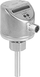 |
Instead of disassembling your system for inline installation, thread these flow switches onto a mounting adapter (sold separately) and insert them into a pipe tee or pipe outlet. They send digital signals to your programmable logic controller (PLC) to activate automated controls or alarms when they reach a set flow rate. To calculate the flow rate, they generate a small amount of heat, then measure the cooling effect your liquid or gas has on it. This makes them ideal in applications with fluctuating temperatures. Use the buttons on the display to adjust the set point and other settings. These switches are accurate in any mounting position.
IP65 rated switches protect against dust and washdowns. IP67 rated switches withstand temporary submersion.
Flow Set Point | 1 13/16" Probe Length | ||||||||||||
|---|---|---|---|---|---|---|---|---|---|---|---|---|---|
For Pipe Size | For Liquids, gpm | For Gas, scfm | Max. Pressure @ Temp. | Temp. Range, ° F | Voltage, V DC | Max. Switching Current @ Voltage | Body Ht. | Enclosure Rating | Certification | Each | |||
304 Stainless Steel Body with 316 Stainless Steel Fittings | |||||||||||||
1 Digital NPN Output Signal | |||||||||||||
| 1/4 1/2 3/4 1 | 0.02 to 1.5 0.05 to 4.9 0.13 to 12.7 0.23 to 23 | 0.14 to 2 0.54 to 8.05 1.21 to 18.11 2.15 to 32.21 | 4,300 psi @ 70° F | -10 to 175 | 36 | 250 mA @ 19V DC 250 mA @ 36V DC | 2 11/16" | IP65, IP67 | C-UL Listed UL Listed CE Marked | 4547N13 | 0000000 | ||
1 Digital PNP Output Signal | |||||||||||||
| 1/4 1/2 3/4 1 | 0.02 to 1.5 0.05 to 4.9 0.13 to 12.7 0.23 to 23 | 0.14 to 2 0.54 to 8.05 1.21 to 18.11 2.15 to 32.21 | 4,300 psi @ 70° F | -10 to 175 | 36 | 250 mA @ 36V DC 250 mA @ 18V DC | 2 11/16" | IP65, IP67 | C-UL Listed UL Listed CE Marked | 4547N11 | 000000 | ||
2 Digital NPN Output Signal | |||||||||||||
| 1/4 1/2 3/4 1 | 0.02 to 1.5 0.05 to 4.9 0.13 to 12.7 0.23 to 23 | 0.14 to 2 0.54 to 8.05 1.21 to 18.11 2.15 to 32.21 | 4,300 psi @ 70° F | -10 to 175 | 36 | 250 mA @ 19V DC 250 mA @ 36V DC | 2 11/16" | IP65, IP67 | C-UL Listed UL Listed CE Marked | 4547N14 | 000000 | ||
2 Digital PNP Output Signal | |||||||||||||
| 1/4 1/2 3/4 1 | 0.02 to 1.5 0.05 to 4.9 0.13 to 12.7 0.23 to 23 | 0.14 to 2 0.54 to 8.05 1.21 to 18.11 2.15 to 32.21 | 4,300 psi @ 70° F | -10 to 175 | 36 | 250 mA @ 36V DC 250 mA @ 18V DC | 2 11/16" | IP65, IP67 | C-UL Listed UL Listed CE Marked | 4547N12 | 000000 | ||
Easy-Hold Abrasive Blaster Safety Switches
 |
Shown in Use |
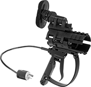
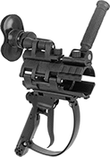
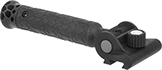
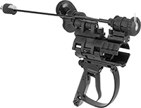
Reduce fatigue during long blasting sessions—these switches are built into a holder for your blaster hose. The holder has a brace that adjusts to shift most of the hose’s thrust away from your arms and grip, and repositions for comfort or different blasting angles. Switch easily between right- and left-hand use without having to take it apart. The housing has upper and lower rail mounts for optional accessories such as a side handle or flashlight (both sold separately). The mounts swivel around the clamp to keep accessories steady as the hose twists during blasting.
Also known as deadman switches, these switches stop blasting if you lose control. They automatically spring back to the off position to prevent injuries and reduce wasted material. To avoid accidental activation, a secondary safety lock requires an additional motion to begin blasting.
Electric
 |
Trigger Actuator |
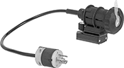
These switches send an electric signal to the control panel on the blaster to stop the spray. Because the signal is electric, these switches respond quickly even when your hose is long. They're recommended for hose that's over 100-ft. long and required by OSHA standards for hose that's over 200-ft. long.
Actuator Style | For Hose OD | Switch Starting Position | No. of Terminals | Switch Designation | Switching Current @ Voltage | Max. Voltage, V DC | Housing Material | Electrical Connection Type | NEMA Type | Wd. | Lg. | Ht. | Features | Each | ||
|---|---|---|---|---|---|---|---|---|---|---|---|---|---|---|---|---|
| Trigger | 1 3/16", 1 1/2", 1 7/8", 2 5/32" | 1 Off | 4 | SPST | 7 amp @ 12V DC 3 amp @ 24V DC | 24 | Plastic | Plug In | L5-15 | 5 1/4" | 11 3/4" | 13" | Adjustable Brace, Secondary Safety Lock, Upper and Lower Rail Mount | 8816N11 | 0000000 |
Tamper-Resistant Line-Voltage Thermostats
 |  |
Thermostat with Tamper-Resistant Guard Removed |
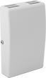
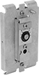
A built-in guard prevents accidental changes and other tampering and protects these thermostats from damage. These thermostats regulate the temperature in HVAC systems that use direct electrical power. They’re often used with baseboard and wall heaters.
Cannot Be Sold To—Energy efficiency requirements restrict sales to the listed jurisdictions/areas.
Overall | |||||||||||||||||
|---|---|---|---|---|---|---|---|---|---|---|---|---|---|---|---|---|---|
Voltage, V AC | Current, amp | Temp. Setting, ° F | Switch Designation | Electrical Connection Type | Ht. | Wd. | Dp. | For Use Outdoors | Mounting Fasteners Included | Features | Display Type | Certification | Cannot Be Sold To | Each | |||
For Heaters | |||||||||||||||||
Dial Control | |||||||||||||||||
| 120 to 277 | 22 | 50 to 90 | SPST | Hardwire | 4 9/16" | 2 13/16" | 1 3/4" | No | No | Tamper-Resistant Guard | Analog | ETL Listed | Colorado | 5474N11 | 000000 | ||
Outdoor High-Current Time and Day Activated Switches
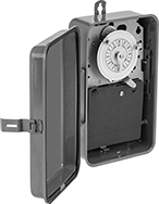 |
Rated NEMA 3R, these rain-tight switches protect against falling liquids and light splashing. They control equipment with high currents, such as landscape lighting, pumps, and heaters. Program them to turn a device on and off at a set time and day. Position trippers around the clock dial to set on and off times.
24-Hr. Timing Cycle—24-hr. switches repeat the same program daily.
Trippers—Additional trippers (sold separately) are sold in pairs that include one “on” tripper and one “off” tripper.
Switches | Trippers | ||||||||||||||||||
|---|---|---|---|---|---|---|---|---|---|---|---|---|---|---|---|---|---|---|---|
No. of Circuits Controlled | Switching Current @ Voltage | Input Voltage, V AC | Max. On/Off Cycles, per day | Min. Set Time, hr. | Tripper Type | No. of Trippers | Housing Material | Switch Designation | Ht. | Wd. | Dp. | Wire Connection | Each | No. of Trippers Included | Pkg. | ||||
24-Hr. Timing Cycle | |||||||||||||||||||
| 1 | 40 amp @ 240V AC | 120 | 12 | 1 | Removable | 2 | Steel | SPST | 9 3/8" | 5 1/2" | 3 5/8" | Screw Terminal | 7037K81 | 0000000 | 1 Pair | 7037K32 | 00000 | ||
Sanitary Electronic Insertion-Mount Flow Switches
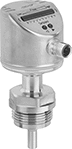 |
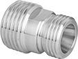
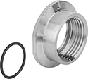
Easy to clean and install, these flow switches are 3-A certified to meet sanitary design standards and insert into your line with a quick-clamp mounting adapter (sold separately). They have a smooth probe, and unlike flow switches that measure with a paddle or turbine, these don’t have moving parts for contaminants to get stuck in. Rated IP67 and IP69K, they withstand temporary submersion and high-temperature, high-pressure washdowns. The mounting adapter attaches to a quick-clamp tube tee or outlet (often called tri-clamp fittings) in your large-diameter tubing system using a gasket and clamp (not included), so you don't need to disassemble your line for inline installation. This mounting adapter is also easy to remove and clean.
They send digital signals to your programmable logic controller (PLC) to activate automated controls or alarms when they reach a set flow rate. To calculate the flow rate, they generate a small amount of heat, then measure the cooling effect your liquid or gas has on it. This makes them ideal in applications with fluctuating temperatures. Use the buttons on the display to adjust the set point and other settings. They’re accurate in any mounting position.
Flow Set Point | 13/16" Probe Length | 1 13/16" Probe Length | ||||||||||||||
|---|---|---|---|---|---|---|---|---|---|---|---|---|---|---|---|---|
For Tube OD | For Liquids, gpm | For Gas, scfm | Max. Pressure @ Temp. | Temp. Range, ° F | Voltage, V DC | Max. Switching Current @ Voltage | Body Ht. | Enclosure Rating | Certification | Food Industry Std. | Each | Each | ||||
316 Stainless Steel Body with 316 Stainless Steel Fittings | ||||||||||||||||
1 Digital PNP Output Signal | ||||||||||||||||
| 1 1/2" 2" | 0.55 to 54.21 0.97 to 96.37 | 4.84 to 72.47 8.59 to 128.84 | 430 psi @ 70° F | -10 to 200 | 36 | 250 mA @ 19V DC 250 mA @ 36V DC | 3 5/16" | IP67, IP69K | C-UL Listed UL Listed CE Marked | 3-A Certified 74-07, FDA Compliant 21 CFR 177.2415 | 4548N11 | 0000000 | 4548N12 | 0000000 | ||
Time-Delay Photoelectric Sensors with Relay Output
 |
Set these sensors to delay activation by up to five seconds after detecting an object. A built-in relay produces AC voltage output. They’re often used with older programmable logic controllers (PLCs). They detect the presence or absence of an object moving at high speeds with a light beam. All are rated IP66 for protection against washdowns.
Direct Sensing—Direct sensing sensors detect objects when light reflects back from the object. The transmitter and receiver are in the same housing, so they fit in confined spaces.
Receiver Sensor—Receiver sensors detect objects when an object breaks the light beam between the transmitter and receiver (both included). They have a longer sensing distance than direct-sensing and reflector sensors.
Reflector Sensor—Reflector sensors detect an object when it passes between the sensor and the reflector, interrupting the beam. They have a longer sensing distance than direct-sensing sensors.
Sensors | Reflectors | |||||||||||||||||
|---|---|---|---|---|---|---|---|---|---|---|---|---|---|---|---|---|---|---|
Reflector | ||||||||||||||||||
Light Beam Switch Operation | Max. Sensing Distance | Switch Designation | Switching Current | Input Voltage | Timer Function | Lg. | Wd. | Ht. | Housing Material | Ht. | Wd. | Temp. Range, ° F | Each | Each | ||||
With Screw Terminals | ||||||||||||||||||
Direct Sensing Sensor with Infrared Light Beam | ||||||||||||||||||
| On When Object Absent, On When Object Present | 39" | SPST | 3 amp, 250V AC, 30V DC | 24V AC to 240V AC/24V DC to 240V DC | Delayed Off Delayed Start (Delay on Make) Switch on (Single Shot) | 2 3/4" | 1" | 2 11/16" | Plastic | — | — | -10 to 130 | 9231K21 | 0000000 | ——— | 0 | ||
Receiver Sensor with Visible Light Beam | ||||||||||||||||||
| On When Object Absent, On When Object Present | 65.5 ft. | SPST | 3 amp, 250V AC, 30V DC | 24V AC to 240V AC/24V DC to 240V DC | Delayed Off Delayed Start (Delay on Make) Switch on (Single Shot) | 2 3/4" | 1" | 2 11/16" | Plastic | — | — | -10 to 130 | 9231K23 | 000000 | ——— | 0 | ||
Reflector Sensor with Visible Light Beam | ||||||||||||||||||
| On When Object Absent, On When Object Present | 23 ft. | SPST | 3 amp, 250V AC, 30V DC | 24V AC to 240V AC/24V DC to 240V DC | Delayed Off Delayed Start (Delay on Make) Switch on (Single Shot) | 2 3/4" | 1" | 2 11/16" | Plastic | 2 3/8" | 1 5/8" | -10 to 130 | 9231K22 | 000000 | 9231K31 | 000000 | ||
