


Filter by
Position Designation
System of Measurement
Switching Voltage
Actuator Style
Switching Current
Switch Action
Wire Connection


Certification

Mounting Location
Illumination
DFARS Specialty Metals
Export Control Classification Number (ECCN)

About Electrical Switches
Choose a switch with the right trigger type, number of inputs, and control functions to power your equipment.
Wet-Environment Toggle Switches
 |  |
Rounded Toggle | Flat Toggle |
A rubber seal protects these switches from splashing water.
IP68 Enclosure Rating, NEMA 4 Enclosure Rating, and NEMA 13 Enclosure Rating—NEMA 4, 13, and IP68 rated switches are protected against oil/coolant spraying, washdowns, and temporary submersion.
On-On—Switches with an on-on or on-(on) position designation alternate power between sets of terminals.
No. of Circuits Controlled | Switch Starting Position | Switch Action | No. of Terminals | Switch Designation | Position Designation | Color | Switching Current @ Voltage | Max. Voltage | For Max. Panel Thk. | Mounting Hardware Included | Mounting Thread Size | Choose a Wire Connection | Each | |||
|---|---|---|---|---|---|---|---|---|---|---|---|---|---|---|---|---|
2 Position with Rounded Toggle—NEMA 4, NEMA 13, IP68 | ||||||||||||||||
For 1/2" Diameter Panel Cutouts | ||||||||||||||||
| 1 | 1 Off | Maintained | 2 | SPST-NO | On-Off | — | 15 amp @ 125V AC, 12 amp @ 28V DC | 28V DC 277V AC | 0.13" | Yes | 15/32"-32 | Quick-Disconnect Terminal, Screw Terminal | 8002K71 | 000000 | ||
| 1 | 1 Off or 1 On | Maintained | 3 | SPDT | On-On | — | 15 amp @ 125V AC, 12 amp @ 28V DC | 28V DC 277V AC | 0.13" | Yes | 15/32"-32 | Quick-Disconnect Terminal, Screw Terminal | 8002K75 | 00000 | ||
| 4 | 4 Off or 4 On | Maintained | 12 | 4PDT | On-On | — | 15 amp @ 125V AC, 12 amp @ 28V DC | 28V DC 277V AC | 0.13" | Yes | 15/32"-32 | Quick-Disconnect Terminal | 8002K381 | 00000 | ||
2 Position with Flat Toggle—NEMA 4, NEMA 13, IP68 | ||||||||||||||||
For 1/2" Diameter Panel Cutouts | ||||||||||||||||
| 1 | 1 Off | Maintained | 2 | SPST-NO | On-Off | Yellow | 15 amp @ 125V AC, 12 amp @ 28V DC | 28V DC 277V AC | 0.13" | Yes | 15/32"-32 | Quick-Disconnect Terminal | 8002K41 | 00000 | ||
3 Position with Rounded Toggle— NEMA 4, NEMA 13, IP68 | ||||||||||||||||
For 1/2" Diameter Panel Cutouts | ||||||||||||||||
| 1 | 1 Off or 1 On | Maintained | 3 | SPDT | On-Off-On | — | 15 amp @ 125V AC, 12 amp @ 28V DC | 28V DC 277V AC | 0.13" | Yes | 15/32"-32 | Quick-Disconnect Terminal, Screw Terminal | 8002K18 | 00000 | ||
Cam Panel-Mount Lever Switches
 |
Lever Switches | Legend Plates | |||||||||||||||
|---|---|---|---|---|---|---|---|---|---|---|---|---|---|---|---|---|
Lever Lg. | No. of Circuits Controlled | Switch Action | No. of Terminals | Position Designation | Message | Switching Current @ Voltage | Max. Voltage | Dia. | Dp. Behind Panel | Each | Message | Each | ||||
2 Positions for 3/8" and 10 mm Diameter Panel Cutouts | ||||||||||||||||
On/Off with Screw Terminals | ||||||||||||||||
| 1 1/2" | 2 | Maintained | 4 | On-Off | 0-1 | 12 amp @ 600V AC | 600V AC 600V DC | 1 1/8" | 1 3/8" | 6958N11 | 000000 | Off-On | 6958N39 | 000000 | ||
| 1 1/2" | 3 | Maintained | 6 | On-Off | 0-1 | 12 amp @ 600V AC | 600V AC 600V DC | 1 1/8" | 1 13/16" | 6958N12 | 00000 | Off-On | 6958N39 | 00000 | ||
3 Positions for 3/8" and 10 mm Diameter Panel Cutouts | ||||||||||||||||
Changeover with Screw Terminals | ||||||||||||||||
| 1 1/2" | 2 | Maintained | 6 | On-Off-On | 1-0-2 | 12 amp @ 600V AC | 600V AC 600V DC | 1 1/8" | 1 13/16" | 6958N16 | 00000 | Hand-Off-Auto | 6958N41 | 00000 | ||
| 1 1/2" | 3 | Maintained | 9 | On-Off-On | 1-0-2 | 12 amp @ 600V AC | 600V AC 600V DC | 1 1/8" | 2 3/16" | 6958N17 | 00000 | Hand-Off-Auto | 6958N41 | 00000 | ||
Selector with Screw Terminals | ||||||||||||||||
| 1 1/2" | 2 | Maintained | 6 | Off-on-On | 0-1-2 | 12 amp @ 600V AC | 600V AC 600V DC | 1 1/8" | 1 13/16" | 6958N23 | 00000 | — | ——— | 0 | ||
| 1 1/2" | 3 | Maintained | 9 | Off-on-On | 0-1-2 | 12 amp @ 600V AC | 600V AC 600V DC | 1 1/8" | 2 3/16" | 6958N24 | 00000 | — | ——— | 0 | ||
4 Positions for 3/8" and 10 mm Diameter Panel Cutouts | ||||||||||||||||
Selector with Screw Terminals | ||||||||||||||||
| 1 1/2" | 1 | Maintained | 4 | Off-on-on-On | 0-1-2-3 | 12 amp @ 600V AC | 600V AC 600V DC | 1 1/8" | 1 13/16" | 6958N29 | 00000 | — | ——— | 0 | ||
5 Positions for 3/8" and 10 mm Diameter Panel Cutouts | ||||||||||||||||
Selector with Screw Terminals | ||||||||||||||||
| 1 1/2" | 1 | Maintained | 5 | Off-on-on-on-On | 0-1-2-3-4 | 12 amp @ 600V AC | 600V AC 600V DC | 1 1/8" | 1 13/16" | 6958N32 | 00000 | — | ——— | 0 | ||
6 Positions for 3/8" and 10 mm Diameter Panel Cutouts | ||||||||||||||||
Selector with Screw Terminals | ||||||||||||||||
| 1 1/2" | 1 | Maintained | 6 | Off-on-on-on-on-On | 0-1-2-3-4-5 | 12 amp @ 600V AC | 600V AC 600V DC | 1 1/8" | 2 3/16" | 6958N33 | 00000 | — | ——— | 0 | ||
Pull-to-Unlock Toggle Switches
 |
Ball-End Toggle |
Prevent accidental actuation—these toggle switches must be pulled out before they can switch a circuit.
Ball-End Toggle—Ball end toggle switches are rated NEMA 4, 13, and IP68 for protection against washdowns, oil/coolant spraying, and temporary submersion.
On-On—Switches with an on-on position designation alternate power between sets of terminals.
No. of Circuits Controlled | Switch Starting Position | Switch Action | No. of Terminals | Switch Designation | Position Designation | Switching Current @ Voltage | Max. Voltage | For Max. Panel Thk. | Mounting Hardware Included | Mounting Thread Size | Wire Connection | Each | |||
|---|---|---|---|---|---|---|---|---|---|---|---|---|---|---|---|
2 Position with Ball-End Toggle—NEMA 4, NEMA 13, IP68 | |||||||||||||||
For 1/2" Diameter Panel Cutouts | |||||||||||||||
| 1 | 1 Off or 1 On | Maintained | 3 | SPDT | On-On | 15 amp @ 125V AC, 12 amp @ 28V DC | 28V DC 277V AC | 0.13" | Yes | 15/32"-32 | Screw Terminal | 7337K97 | 000000 | ||
3 Position with Ball-End Toggle—NEMA 4, NEMA 13, IP68 | |||||||||||||||
For 1/2" Diameter Panel Cutouts | |||||||||||||||
| 1 | 1 Off or 1 On | Maintained | 3 | SPDT | On-Off-On | 15 amp @ 125V AC, 12 amp @ 28V DC | 28V DC 277V AC | 0.13" | Yes | 15/32"-32 | Screw Terminal | 7337K95 | 00000 | ||
Rocker Switches
 |
Style A |
The wide surface of these switches makes them easy to press on and off, even if your hands are full and you need to use an elbow. They’re often used as power switches on electronic devices and control panels.
Note: Illuminated switches include a bulb. If wiring the switch and the bulb to the same circuit, the circuit voltage must not exceed the bulb voltage.
For 13/16" Diameter Panel Cutouts—Switches for a 13/16” dia. panel cutout are round, so you can use a drill bit or knockout to install them instead of cutting a rectangular hole.
Style | No. of Circuits Controlled | Switch Starting Position | Switch Action | No. of Terminals | Switch Designation | Position Designation | Switching Current @ Voltage | Max. Voltage, V AC | Quick-Disconnect Tab Wd. | Color | Each | |||
|---|---|---|---|---|---|---|---|---|---|---|---|---|---|---|
2 Positions with Quick-Disconnect Terminals | ||||||||||||||
For 13/16" Diameter Panel Cutouts | ||||||||||||||
| A | 1 | 1 On | Maintained | 2 | SPST-NC | On-Off | 20 amp @ 125V AC, 12 amp @ 250V AC | 250 | 0.189" | Black | 7395K131 | 00000 | ||
Mil. Spec. Washdown Toggle Switches
 |
These switches meet MIL-S-3950. A rubber seal protects them from washdowns.
On-On—Switches with an on-on, on-on-on, or (on)-on-on position designation alternate power between sets of terminals.
No. of Circuits Controlled | Switch Starting Position | Switch Action | No. of Terminals | Switch Designation | Position Designation | Switching Current @ Voltage | Max. Voltage | Dp. Behind Panel | Mounting Hardware Included | Wire Connection | Each | |||
|---|---|---|---|---|---|---|---|---|---|---|---|---|---|---|
2 Positions | ||||||||||||||
For 1/2" Diameter Panel Cutouts | ||||||||||||||
| 4 | 4 Off | Maintained | 8 | 4PST | On-Off | 15 amp @ 125V AC, 12 amp @ 28V DC | 28V DC 125V AC | 1.35" | Yes | Screw Terminal | 8002K134 | 000000 | ||
| 4 | 4 Off or 4 On | Maintained | 12 | 4PDT | On-On | 15 amp @ 125V AC, 12 amp @ 28V DC | 28V DC 125V AC | 1.35" | Yes | Screw Terminal | 8002K135 | 00000 | ||
3 Positions | ||||||||||||||
For 1/2" Diameter Panel Cutouts | ||||||||||||||
| 4 | 4 Off or 4 On | Maintained | 12 | 4PDT | On-Off-On | 15 amp @ 125V AC, 12 amp @ 28V DC | 28V DC 125V AC | 1.35" | Yes | Screw Terminal | 8002K133 | 00000 | ||
Panel-Mount Compact Disconnect Switches
Maintained Switch%20--%3e%3csvg%20version='1.1'%20id='Layer_1'%20xmlns='http://www.w3.org/2000/svg'%20xmlns:xlink='http://www.w3.org/1999/xlink'%20x='0px'%20y='0px'%20viewBox='0%200%20400%20400'%20style='enable-background:new%200%200%20400%20400;'%20xml:space='preserve'%3e%3cstyle%20type='text/css'%3e%20.st0{fill:%231A70A0;}%20.st1{opacity:0.5;}%20%3c/style%3e%3cg%3e%3cg%3e%3cpath%20class='st0'%20d='M200,56.9c38.35,0,74.4,14.93,101.51,42.05c27.11,27.11,42.05,63.17,42.05,101.51s-14.93,74.4-42.05,101.51%20S238.35,344.02,200,344.02s-74.4-14.93-101.51-42.05c-27.11-27.11-42.05-63.17-42.05-101.51s14.93-74.4,42.05-101.51%20S161.65,56.9,200,56.9%20M200,12.9C96.41,12.9,12.44,96.88,12.44,200.46c0,103.59,83.97,187.56,187.56,187.56%20c103.59,0,187.56-83.97,187.56-187.56C387.56,96.88,303.59,12.9,200,12.9L200,12.9z'/%3e%3c/g%3e%3cg%3e%3cg%20class='st1'%3e%3cpath%20class='st0'%20d='M235.49,152.24h16.15l-27.46,111.87c-1.94,7.8-2.91,12.5-2.91,14.1c0,1.82,0.58,3.29,1.73,4.41%20c1.16,1.12,2.69,1.68,4.61,1.68c5.23,0,11.78-3.85,19.63-11.55l17.22,21.34c-16.95,17.33-34.87,26-53.78,26%20c-8.37,0-15.45-1.47-21.23-4.41c-5.79-2.94-10.44-7.25-13.95-12.92c-3.51-5.67-5.27-11.18-5.27-16.53c0-1.93,0.35-5.24,1.05-9.94%20c1-6.94,2.05-12.54,3.15-16.82l15.22-62.15h-32.69l7.65-30.97C190.89,163.58,214.53,158.88,235.49,152.24z%20M230.44,80.84%20c8.24,0,14.66,2.62,19.26,7.86c4.6,5.24,6.9,11.55,6.9,18.94c0,5.46-1.42,10.7-4.25,15.73c-2.83,5.03-6.88,9.07-12.12,12.12%20c-5.24,3.05-10.33,4.57-15.24,4.57c-4.6,0-9.17-1.23-13.72-3.69c-4.55-2.46-8.02-5.78-10.43-9.95%20c-2.41-4.17-3.61-8.67-3.61-13.48c0-5.35,1.52-10.64,4.57-15.89c3.05-5.24,7.03-9.25,11.96-12.04%20C218.68,82.23,224.24,80.84,230.44,80.84z'/%3e%3c/g%3e%3cg%3e%3cpath%20class='st0'%20d='M214.08,152.24h16.15l-27.46,111.87c-1.94,7.8-2.91,12.5-2.91,14.1c0,1.82,0.58,3.29,1.73,4.41%20c1.16,1.12,2.69,1.68,4.61,1.68c5.23,0,11.78-3.85,19.63-11.55l17.22,21.34c-16.95,17.33-34.87,26-53.78,26%20c-8.37,0-15.45-1.47-21.23-4.41c-5.79-2.94-10.44-7.25-13.95-12.92c-3.51-5.67-5.27-11.18-5.27-16.53c0-1.93,0.35-5.24,1.05-9.94%20c1-6.94,2.05-12.54,3.15-16.82l15.22-62.15h-32.69l7.65-30.97C169.48,163.58,193.11,158.88,214.08,152.24z%20M209.03,80.84%20c8.24,0,14.66,2.62,19.26,7.86c4.6,5.24,6.9,11.55,6.9,18.94c0,5.46-1.42,10.7-4.25,15.73c-2.83,5.03-6.88,9.07-12.12,12.12%20c-5.24,3.05-10.33,4.57-15.24,4.57c-4.6,0-9.17-1.23-13.72-3.69c-4.55-2.46-8.02-5.78-10.43-9.95%20c-2.41-4.17-3.61-8.67-3.61-13.48c0-5.35,1.52-10.64,4.57-15.89c3.05-5.24,7.03-9.25,11.96-12.04%20C197.26,82.23,202.83,80.84,209.03,80.84z'/%3e%3c/g%3e%3c/g%3e%3c/g%3e%3c/svg%3e)
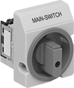 |
Lockout—All switches have a lockout so you can secure them in the off position with a padlock (not included).
IP65 Enclosure Rating—They’re rated IP65 for protection from washdowns.
Switching Current @ Voltage | Switch Designation | Electrical Phase (hp) | Ht. | Wd. | Dp. Behind Panel | For Max. Padlock Shackle Dia. | Enclosure Rating | Certification | Specs. Met | Each | |||
|---|---|---|---|---|---|---|---|---|---|---|---|---|---|
Gray Plastic Housing with Black Actuator | |||||||||||||
3 Circuits Controlled with Lockout—For 3/8" Dia. Panel Cutouts | |||||||||||||
| 12 amp @ 600V AC, 16 amp @ 24V DC | 3PST | Single (1/2 hp @ 120V AC) Three (1 hp @ 120V AC) Three (3 hp @ 240V AC) | 3 1/4" | 2 1/2" | 1 13/16" | 5/16" | IP65 | UL Recognized Component | UL 508 | 65915K101 | 000000 | ||
4 Circuits Controlled with Lockout—For 3/8" Dia. Panel Cutouts | |||||||||||||
| 12 amp @ 600V AC, 16 amp @ 24V DC | 4PST | Single (1/2 hp @ 120V AC) Three (1 hp @ 120V AC) Three (3 hp @ 240V AC) | 3 1/4" | 2 1/2" | 1 13/16" | 5/16" | IP65 | UL Recognized Component | UL 508 | 65915K107 | 00000 | ||
Yellow Plastic Housing with Red Actuator | |||||||||||||
3 Circuits Controlled with Lockout—For 3/8" Dia. Panel Cutouts | |||||||||||||
| 12 amp @ 600V AC, 16 amp @ 24V DC | 3PST | Single (1/2 hp @ 120V AC) Three (1 hp @ 120V AC) Three (3 hp @ 240V AC) | 3 1/4" | 2 1/2" | 1 13/16" | 5/16" | IP65 | UL Recognized Component | UL 508 | 65915K11 | 00000 | ||
4 Circuits Controlled with Lockout—For 3/8" Dia. Panel Cutouts | |||||||||||||
| 12 amp @ 600V AC, 16 amp @ 24V DC | 4PST | Single (1/2 hp @ 120V AC) Three (1 hp @ 120V AC) Three (3 hp @ 240V AC) | 3 1/4" | 2 1/2" | 1 13/16" | 5/16" | IP65 | UL Recognized Component | UL 508 | 65915K41 | 00000 | ||
Enclosed Compact Disconnect Switches
Maintained Switch
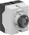 |
Plastic Housing—Their plastic housing protects the switch and resists denting, chipping, and cracking.
Lockout—All switches have a lockout so you can secure them in the off position with a padlock (not included).
IP65 Enclosure Rating—Rated IP65, the housing also seals out water even in frequently washed down areas.
Switching Current @ Voltage | Switch Designation | Electrical Phase (hp) | Ht. | Wd. | For Max. Padlock Shackle Dia. | Enclosure Rating | Certification | Specs. Met | Each | |||
|---|---|---|---|---|---|---|---|---|---|---|---|---|
Yellow Plastic Housing with Red Actuator | ||||||||||||
3 Circuits Controlled with Lockout | ||||||||||||
| 12 amp @ 600V AC, 16 amp @ 24V DC | 3PST | Single (1/2 hp @ 120V AC) Three (1 hp @ 120V AC) Three (3 hp @ 240V AC) | 4 3/4" | 3 13/16" | 5/16" | IP65 | UL Recognized Component, CSA Certified | UL 508 | 65915K21 | 0000000 | ||
4 Circuits Controlled with Lockout | ||||||||||||
| 12 amp @ 600V AC, 16 amp @ 24V DC | 4PST | Single (1/2 hp @ 120V AC) Three (1 hp @ 120V AC) Three (3 hp @ 240V AC) | 4 3/4" | 3 13/16" | 5/16" | IP65 | UL Recognized Component, CSA Certified | — | 65915K34 | 000000 | ||
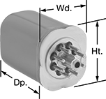
Compact Spade-Terminal Relays
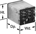 | 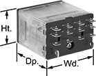 | 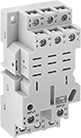 |
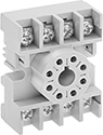
11-Terminal Relay | 14-Terminal Relay | 11-Terminal Relay Socket |
 | 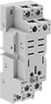 | |
14-Terminal Relay Socket | 8-Terminal Relay Socket |
Fit these relays where standard spade-terminal relays are too big. You can connect them three ways. Plug them into a socket (sold separately), connect them with quick-disconnect terminals, or solder wires directly to the terminals. An LED indicator shows you the status of the relay, so you know it’s connected and wired correctly.
2 Circuits Controlled, 3 Circuits Controlled, and 4 Circuits Controlled—Relays that control 2 or more circuits have a lockable test button, so you can test their function. When you press the button, the relay switches contacts. Use this button when checking a relay for proper function before installing it, or when investigating issues with wired relays.
Sockets with Screw Terminals—Relay sockets mount directly on 35 mm DIN rail (also known as DIN 3 rail) for fast installation. You can also mount them to a flat surface using screws.
Relays | Sockets with Screw Terminals | |||||||||||||||
|---|---|---|---|---|---|---|---|---|---|---|---|---|---|---|---|---|
No. of Terminals | Input Voltage | Control Current, mA | Switching Current @ Voltage | Max. Switching Voltage, V AC | hp @ Switching Voltage | Ht. | Wd. | Dp. | Quick-Disconnect Tab Wd. | Features | Each | Each | ||||
2 Circuits Controlled with 2 Off or 2 On—DPDT | ||||||||||||||||
Relay-Socket Mount | ||||||||||||||||
| 8 | 24V AC | 50 | 15 amp @ 120V AC 12 amp @ 24V DC | 300 | 1/2 hp @ 120V AC 1 hp @ 277V AC | 1.1" | 0.9" | 1.6" | 0.187" | LED Indicator, Lockable Test Button, Mechanical Flag Indicator | 69585K57 | 000000 | 69585K1 | 00000 | ||
| 8 | 120V AC | 10 | 15 amp @ 120V AC 12 amp @ 24V DC | 300 | 1/2 hp @ 120V AC 1 hp @ 277V AC | 1.1" | 0.9" | 1.6" | 0.187" | LED Indicator, Lockable Test Button, Mechanical Flag Indicator | 69585K58 | 00000 | 69585K1 | 0000 | ||
| 8 | 240V AC | 5 | 15 amp @ 120V AC 12 amp @ 24V DC | 300 | 1/2 hp @ 120V AC 1 hp @ 277V AC | 1.1" | 0.9" | 1.6" | 0.187" | LED Indicator, Lockable Test Button, Mechanical Flag Indicator | 69585K59 | 00000 | 69585K1 | 0000 | ||
| 8 | 12V DC | 75 | 15 amp @ 120V AC 12 amp @ 24V DC | 300 | 1/2 hp @ 120V AC 1 hp @ 277V AC | 1.1" | 0.9" | 1.6" | 0.187" | LED Indicator, Lockable Test Button, Mechanical Flag Indicator | 69585K66 | 00000 | 69585K1 | 0000 | ||
| 8 | 24V DC | 38 | 15 amp @ 120V AC 12 amp @ 24V DC | 300 | 1/2 hp @ 120V AC 1 hp @ 277V AC | 1.1" | 0.9" | 1.6" | 0.187" | LED Indicator, Lockable Test Button, Mechanical Flag Indicator | 69585K67 | 00000 | 69585K1 | 0000 | ||
3 Circuits Controlled with 3 Off or 3 On—3PDT | ||||||||||||||||
Relay-Socket Mount | ||||||||||||||||
| 11 | 24V AC | 63 | 15 amp @ 120V AC 12 amp @ 24V DC | 300 | 1/2 hp @ 120V AC 1 hp @ 277V AC | 1.1" | 1.2" | 1.6" | 0.187" | LED Indicator, Lockable Test Button, Mechanical Flag Indicator | 69585K68 | 00000 | 69585K2 | 00000 | ||
| 11 | 120V AC | 13 | 15 amp @ 120V AC 12 amp @ 24V DC | 300 | 1/2 hp @ 120V AC 1 hp @ 277V AC | 1.1" | 1.2" | 1.6" | 0.187" | LED Indicator, Lockable Test Button, Mechanical Flag Indicator | 69585K69 | 00000 | 69585K2 | 00000 | ||
| 11 | 240V AC | 6 | 15 amp @ 120V AC 12 amp @ 24V DC | 300 | 1/2 hp @ 120V AC 1 hp @ 277V AC | 1.1" | 1.2" | 1.6" | 0.187" | LED Indicator, Lockable Test Button, Mechanical Flag Indicator | 69585K71 | 00000 | 69585K2 | 00000 | ||
| 11 | 12V DC | 117 | 15 amp @ 120V AC 12 amp @ 24V DC | 300 | 1/2 hp @ 120V AC 1 hp @ 277V AC | 1.1" | 1.2" | 1.6" | 0.187" | LED Indicator, Lockable Test Button, Mechanical Flag Indicator | 69585K72 | 00000 | 69585K2 | 00000 | ||
| 11 | 24V DC | 58 | 15 amp @ 120V AC 12 amp @ 24V DC | 300 | 1/2 hp @ 120V AC 1 hp @ 277V AC | 1.1" | 1.2" | 1.6" | 0.187" | LED Indicator, Lockable Test Button, Mechanical Flag Indicator | 69585K73 | 00000 | 69585K2 | 00000 | ||
4 Circuits Controlled with 4 Off or 4 On—4PDT | ||||||||||||||||
Relay-Socket Mount | ||||||||||||||||
| 14 | 24V AC | 63 | 15 amp @ 120V AC 12 amp @ 24V DC | 300 | 1/2 hp @ 120V AC 1 hp @ 277V AC | 1.1" | 1.6" | 1.6" | 0.187" | LED Indicator, Lockable Test Button, Mechanical Flag Indicator | 69585K74 | 00000 | 69585K3 | 00000 | ||
| 14 | 120V AC | 13 | 15 amp @ 120V AC 12 amp @ 24V DC | 300 | 1/2 hp @ 120V AC 1 hp @ 277V AC | 1.1" | 1.6" | 1.6" | 0.187" | LED Indicator, Lockable Test Button, Mechanical Flag Indicator | 69585K79 | 00000 | 69585K3 | 00000 | ||
| 14 | 12V DC | 125 | 15 amp @ 120V AC 12 amp @ 24V DC | 300 | 1/2 hp @ 120V AC 1 hp @ 277V AC | 1.1" | 1.6" | 1.6" | 0.187" | LED Indicator, Lockable Test Button, Mechanical Flag Indicator | 69585K55 | 00000 | 69585K3 | 00000 | ||
| 14 | 24V DC | 6 | 15 amp @ 120V AC 12 amp @ 24V DC | 300 | 1/2 hp @ 120V AC 1 hp @ 277V AC | 1.1" | 1.6" | 1.6" | 0.187" | LED Indicator, Lockable Test Button, Mechanical Flag Indicator | 69585K96 | 00000 | 69585K3 | 00000 | ||
Hazardous Location Relays
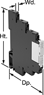 | 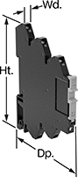 |
Screw Terminals | Spring-Clamp Terminals |
 |  |
Circular-Pin Terminals—Hermetically Sealed | Sockets with Screw Terminals |
Sealed for safety, these relays are a good choice for hazardous locations where combustible or corrosive gases may be present.
Screw Terminals—Relays with screw terminals are considered interface relays, so they’re placed between your controller and components to isolate the input and output circuits. This means they protect your component from voltage spikes while amplifying the relay’s signal and reducing interference for reliable transmission. They are often used for switching applications, such as small motors and pilot lights. The included relay socket mounts on 35 mm DIN rail (also known as DIN 3 rail).
Spring-Clamp Terminals—Relays with spring-clamp terminals are considered interface relays, so they’re placed between your controller and components to isolate the input and output circuits. This means they protect your component from voltage spikes while amplifying the relay’s signal and reducing interference for reliable transmission. They are often used for switching applications, such as small motors and pilot lights. The included relay socket mounts on 35 mm DIN rail (also known as DIN 3 rail). Relays with spring-clamp terminals connect and disconnect to wires without needing to turn screws. With no screws to shake loose with vibration, the terminals hold tight over time.
Circular-Pin Terminal—Relays with circular-pin terminals or quick-disconnect terminals are hermetically sealed—completely air- and watertight—to shield internal parts from gases, moisture, and other contaminants. They plug into relay sockets (sold separately) for easy installation.
Sockets with Screw Terminals—Relay sockets mount to 35 mm DIN rail (also known as DIN 3 rail) or flat surfaces.
Relays | Sockets with Screw Terminals | |||||||||||||||
|---|---|---|---|---|---|---|---|---|---|---|---|---|---|---|---|---|
No. of Terminals | Input Voltage | Control Current, mA | Switching Current @ Voltage | Max. Switching Voltage | hp @ Switching Voltage | Ht. | Wd. | Dp. | Enclosure Rating | Hazardous Location Rating | Each | Each | ||||
Screw Terminals | ||||||||||||||||
1 Circuit Controlled with 1 Off or 1 On—SPDT | ||||||||||||||||
| 5 | 12V AC, 12V DC | 29 | 12 amp @ 240V AC/24V DC | 400V AC/300V DC | — | 2.9" | 0.6" | 3.5" | IP20 | NEC Class I Division 2 Groups A, B, C, D | 4190N312 | 000000 | ——— | 0 | ||
Spring-Clamp Terminals | ||||||||||||||||
1 Circuit Controlled with 1 Off or 1 On—SPDT | ||||||||||||||||
| 5 | 12V AC, 12V DC | 29 | 12 amp @ 240V AC/24V DC | 400V AC/300V DC | — | 2.9" | 0.6" | 3.7" | IP20 | NEC Class I Division 2 Groups A, B, C, D | 8163N14 | 00000 | ——— | 0 | ||
| 5 | 24V AC, 24V DC | 20 | 12 amp @ 240V AC/24V DC | 400V AC/300V DC | — | 2.9" | 0.6" | 3.7" | IP20 | NEC Class I Division 2 Groups A, B, C, D | 8163N15 | 00000 | ——— | 0 | ||
| 5 | 120V AC, 120V DC | 4 | 12 amp @ 240V AC/24V DC | 400V AC/300V DC | — | 2.9" | 0.6" | 3.7" | IP20 | NEC Class I Division 2 Groups A, B, C, D | 8163N16 | 00000 | ——— | 0 | ||
Circular-Pin Terminals—Hermetically Sealed | ||||||||||||||||
2 Circuits Controlled with 2 Off or 2 On—DPDT | ||||||||||||||||
| 8 | 120V AC | 10 | 12 amp @ 120V AC/24V DC | 300V AC | 1/3 hp @ 120V AC | 1.6" | 1.4" | 2.1" | — | NEC Class I Division 2 Groups A, B, C, D | 7125T32 | 000000 | 7125T41 | 00000 | ||
| 8 | 24V DC | 38 | 12 amp @ 120V AC/24V DC | 300V AC | 1/3 hp @ 120V AC | 1.6" | 1.4" | 2.1" | — | NEC Class I Division 2 Groups A, B, C, D | 7125T34 | 000000 | 7125T41 | 0000 | ||
3 Circuits Controlled with 3 Off or 3 On—3PDT | ||||||||||||||||
| 11 | 120V AC | 100 | 12 amp @ 120V AC/240V AC | 300V AC | 1/3 hp @ 120V AC | 1.6" | 1.4" | 2.1" | — | NEC Class I Division 2 Groups A, B, C, D | 7125T111 | 000000 | 7122K21 | 0000 | ||
Safety Relays
SIL 3, PLe, Cat. 4 Max. System Safety Rating—DIN-Rail Mount, Surface Mount
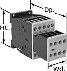 |
Relays that meet SIL 3 are tested for applications with a probability of failure of 0.01% to 0.1% and are used for preventing fires, explosions, or toxic releases.
Relays that meet Cat. 4 withstand circuit surges in electrical applications up to 600V.
Mirror Auxiliary Contacts—Relays with mirror auxiliary contacts have contacts that are normally closed and cannot be open at the same time as a normally open main contact.
Nondetachable Auxiliary Contacts—Relays with nondetachable contacts have auxiliary contacts that won’t separate from the relay if there is shock or vibration.
Self-Monitoring Circuitry—When a failure is detected, relays with self-monitoring circuitry signal the controller to remove power and prevent restarting until the issue is resolved.
hp @ Switching Voltage | |||||||||||||||
|---|---|---|---|---|---|---|---|---|---|---|---|---|---|---|---|
No. of Terminals | Input Voltage | Control Current, mA | Switching Current @ Voltage | Max. Switching Voltage, V AC | Single Phase | Three Phase | Aux. Contact Switch Starting Position | Ht. | Wd. | Dp. | Features | Each | |||
Screw-Terminal Wire Connection | |||||||||||||||
3 Circuits Controlled with 3 Off—3PST-NO | |||||||||||||||
| 18 | 120V AC | 2 | 12 amp @ 400V AC | 600 | 1 hp @ 120V AC 2 hp @ 240V AC | 3 hp @ 240V AC 10 hp @ 480V AC 10 hp @ 600V AC | 2 Off and 3 On | 2.7" | 1.8" | 4.6" | Inspection Window, Interlocked Opposing Contacts, Mirror Auxiliary Contacts, Nondetachable Auxiliary Contacts, Recessed Terminals, Self-Monitoring Circuitry | 6242N13 | 0000000 | ||
| 18 | 24V DC | 18 | 12 amp @ 400V AC | 600 | 1 hp @ 120V AC 2 hp @ 240V AC | 3 hp @ 240V AC 10 hp @ 480V AC 10 hp @ 600V AC | 2 Off and 3 On | 2.7" | 1.8" | 4.6" | Inspection Window, Interlocked Opposing Contacts, Mirror Auxiliary Contacts, Nondetachable Auxiliary Contacts, Recessed Terminals, Self-Monitoring Circuitry | 6242N17 | 000000 | ||
Network-Enabled Relays
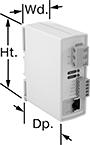 |
1 Circuit Controlled |
With a built-in web server, these relays can be remotely controlled over any IP network, including the Internet. They connect to your network either wirelessly or with an Ethernet cable (not included). No programming or software is required to operate these relays. Instead, use your web browser to input the relay’s IP address and the website guides you through simple menus and drop-down lists to set your parameters. Alternatively, you can use these relays with a PLC or without a computer at all if you use one relay as a controller for another relay.
Each circuit has a digital input that can be used to control the relay or a remote relay over the IP network. You could also use the digital input to monitor a separate device, such as a push-button or door alarm switch. These relays can be set to automatically restart network devices, such as computers, even when they fail to respond to relay signals. LED indicators let you know if there’s input and output voltage and if the network is connected and active. All meet at least one safety standard.
Mount these relays on 35 mm DIN rail (also known as DIN 3 rail) for fast installation. They also mount to flat surfaces.
Power Over Ethernet Standard—Power over Ethernet (PoE) compatible relays can receive power from PoE cables (not included).
Digital Inputs | Digital Outputs | ||||||||||||||||||
|---|---|---|---|---|---|---|---|---|---|---|---|---|---|---|---|---|---|---|---|
No. of Terminals | Voltage | No. of | Voltage | No. of | Control Current, amp | Switching Current @ Voltage | Max. Switching Voltage, V DC | Ht. | Wd. | Dp. | Signal Type | PoE Std. | Control Communication Protocol | Operating System Compatibility | Features | Each | |||
1 Circuit Controlled with 1 Off or 1 On—SPDT | |||||||||||||||||||
| 8 | 6V DC 9V DC 12V DC 24V DC | 1 | 5V DC | 1 | 12 | 12 amp @ 30V DC | 30 | 3.9" | 1.4" | 3.1" | Data | — | Modbus TCP/IP | Android 6.0 or Later, iOS 9.0 or Later, Windows XP or Later | LED Indicators | 7059N11 | 0000000 | ||
| 8 | 6V DC 9V DC 12V DC 24V DC | 1 | 5V DC | 1 | 12 | 12 amp @ 30V DC | 30 | 3.9" | 1.4" | 3.1" | Data | PoE Type 1 | Modbus TCP/IP | Android 6.0 or Later, iOS 9.0 or Later, Windows XP or Later | LED Indicators | 7059N12 | 000000 | ||
