


Filter by
Actuator Style

Position Designation
Switch Action
Switching Current
Wire Connection
Electrical Connection
Switch Starting Position
Mounting Thread Size
Panel Cutout Width
Export Control Classification Number (ECCN)
U.S.–Mexico–Canada Agreement (USMCA) Qualifying
DFARS Specialty Metals

About Electrical Switches
Choose a switch with the right trigger type, number of inputs, and control functions to power your equipment.
Miniature Toggle Switches
 |
Maximize the space in a panel—these switches are half the size of most toggle switches.
On-(On) and On-On—Switches with an on-on or on-(on) position designation alternate power between sets of terminals.
Wire Leads | |||||||||||||||||
|---|---|---|---|---|---|---|---|---|---|---|---|---|---|---|---|---|---|
No. of Circuits Controlled | Switch Starting Position | Switch Action | No. of Terminals | Switch Designation | Position Designation | Switching Current @ Voltage | Max. Voltage | For Max. Panel Thk. | No. of | Lg. | Mounting Hardware Included | Mounting Thread Size | Choose a Wire Connection | Each | |||
2 Position with Rounded Toggle | |||||||||||||||||
For 1/4" Diameter Panel Cutouts | |||||||||||||||||
| 1 | 1 Off | Maintained | 2 | SPST-NO | On-Off | 6 amp @ 125V AC, 4 amp @ 30V DC | 30V DC 250V AC | 0.1" | 2 | 12" | Yes | 1/4"-40 | Wire Leads | 7172K61 | 000000 | ||
| 1 | 1 Off or 1 On | Maintained | 3 | SPDT | On-On | 6 amp @ 125V AC, 4 amp @ 30V DC | 30V DC 250V AC | 0.16" | — | — | Yes | 1/4"-40 | Quick-Disconnect Terminal, Tab | 7347K75 | 00000 | ||
| 1 | 1 Off or 1 On | Momentary | 3 | SPDT | On-(On) | 6 amp @ 125V AC, 4 amp @ 30V DC | 30V DC 250V AC | 0.16" | — | — | Yes | 1/4"-40 | Quick-Disconnect Terminal, Tab | 7347K76 | 00000 | ||
| 2 | 2 Off or 2 On | Maintained | 6 | DPDT | On-On | 6 amp @ 125V AC, 4 amp @ 30V DC | 30V DC 250V AC | 0.16" | — | — | Yes | 1/4"-40 | Quick-Disconnect Terminal, Tab | 7347K82 | 00000 | ||
| 2 | 2 Off or 2 On | Momentary | 6 | DPDT | On-(On) | 6 amp @ 125V AC, 4 amp @ 30V DC | 30V DC 250V AC | 0.16" | — | — | Yes | 1/4"-40 | Tab | 7347K24 | 00000 | ||
| 3 | 3 Off or 3 On | Maintained | 9 | 3PDT | On-On | 6 amp @ 125V AC, 4 amp @ 30V DC | 30V DC 250V AC | 0.16" | — | — | Yes | 1/4"-40 | Tab | 7347K96 | 00000 | ||
| 4 | 4 Off or 4 On | Maintained | 12 | 4PDT | On-On | 6 amp @ 125V AC, 4 amp @ 30V DC | 30V DC 250V AC | 0.16" | — | — | Yes | 1/4"-40 | Tab | 7347K99 | 00000 | ||
3 Position with Rounded Toggle | |||||||||||||||||
For 1/4" Diameter Panel Cutouts | |||||||||||||||||
| 1 | 1 Off or 1 On | Maintained | 3 | SPDT | On-Off-On | 6 amp @ 125V AC, 4 amp @ 30V DC | 30V DC 250V AC | 0.16" | — | — | Yes | 1/4"-40 | Quick-Disconnect Terminal, Tab | 7347K73 | 00000 | ||
| 1 | 1 Off or 1 On | Momentary | 3 | SPDT | (On)-Off-(On) | 6 amp @ 125V AC, 4 amp @ 30V DC | 30V DC 250V AC | 0.16" | — | — | Yes | 1/4"-40 | Quick-Disconnect Terminal, Tab | 7347K74 | 00000 | ||
| 2 | 2 Off or 2 On | Maintained | 6 | DPDT | On-Off-On | 6 amp @ 125V AC, 4 amp @ 30V DC | 30V DC 250V AC | 0.16" | — | — | Yes | 1/4"-40 | Quick-Disconnect Terminal, Tab | 7347K79 | 00000 | ||
| 2 | 2 Off or 2 On | Momentary | 6 | DPDT | (On)-Off-(On) | 6 amp @ 125V AC, 4 amp @ 30V DC | 30V DC 250V AC | 0.16" | — | — | Yes | 1/4"-40 | Quick-Disconnect Terminal, Tab | 7347K81 | 00000 | ||
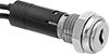
Low-Voltage 19 mm Panel-Mount Push-Button Doorbell Switches
 |
Operate low-voltage devices that require less than 48 volts, such as doorbells and buzzers. These switches have one input terminal and three output terminals to control up to three devices at once.
No. of Circuits Controlled | Switch Starting Position | Switch Action | No. of Terminals | Switch Designation | Actuator Color | Switching Current @ Voltage | Max. Voltage | Dia. | Dp. Behind Panel | Each | |||
|---|---|---|---|---|---|---|---|---|---|---|---|---|---|
Metal Actuator Base with Screw-Terminal Wire Connection | |||||||||||||
Projecting Snap In | |||||||||||||
| 1 | 1 Off | Momentary | 4 | SPST-NO | Black | 4 amp @ 24V AC, 1 amp @ 24V DC | 48V AC 48V DC | 1" | 1 1/16" | 69755K64 | 000000 | ||
Miniature Rocker Switches
 | |
Switches with Tab Terminals | Switches with Wire Leads |
Maximize space in a panel—these switches are smaller than most standard rocker switches.
Note: Illuminated switches include a bulb. If wiring the switch and the bulb to the same circuit, the circuit voltage must not exceed bulb voltage.
On-On—Switches with an on-on position designation alternate power between sets of terminals.
Wire Leads | ||||||||||||||
|---|---|---|---|---|---|---|---|---|---|---|---|---|---|---|
No. of Circuits Controlled | Switch Starting Position | Switch Action | No. of Terminals | Switch Designation | Position Designation | Switching Current @ Voltage | Max. Voltage | No. of | Lg. | Color | Each | |||
2 Positions with Tab Terminals | ||||||||||||||
For 3/4" High × 9/32" Wide Panel Cutouts | ||||||||||||||
| 1 | 1 Off or 1 On | Maintained | 3 | SPDT | On-On | 6 amp @ 125V AC, 4 amp @ 28V DC | 250V AC, 30V DC | — | — | Black | 7395K35 | 00000 | ||
2 Positions with Wire Leads | ||||||||||||||
For 3/4" High × 9/32" Wide Panel Cutouts | ||||||||||||||
| 1 | 1 Off or 1 On | Maintained | 3 | SPDT | On-On | 6 amp @ 125V AC, 4 amp @ 28V DC | 250V AC, 30V DC | 3 | 12" | Black | 7395K65 | 00000 | ||
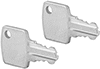
3/4" Panel-Mount Key Switches
 |
Tab Wire Connection |
Prevent accidental activation and limit access—these switches require a key to turn circuits on or off. All fit into a standard panel cutout.
Keyed Alike—Keyed alike switches all open with the same key.
Key Switches | Replacement Keys | |||||||||||||||
|---|---|---|---|---|---|---|---|---|---|---|---|---|---|---|---|---|
No. of Circuits Controlled | Switch Starting Position | Switch Action | No. of Terminals | Switch Designation | Switching Current @ Voltage | Max. Voltage | Dia. | Dp. Behind Panel | No. of Keys Included | Key Removal Position | Each | Each | ||||
2 Positions with Metal Actuator Base | ||||||||||||||||
Keyed Alike with Tab Wire Connection | ||||||||||||||||
| 1 | 1 Off or 1 On | Maintained | 3 | SPDT | 4 amp @ 125V AC/24V DC | 125V AC 28V DC | 7/8" | 1 1/16" | 2 | Center | 7278K12 | 000000 | 7278K2 | 00000 | ||
| 1 | 1 Off or 1 On | Maintained | 3 | SPDT | 4 amp @ 125V AC/24V DC | 125V AC 28V DC | 7/8" | 1 1/16" | 2 | Center, Right | 7278K13 | 00000 | 7278K3 | 0000 | ||
| 2 | 2 Off or 2 On | Maintained | 6 | DPDT | 4 amp @ 125V AC/24V DC | 125V AC 28V DC | 7/8" | 1 1/16" | 2 | Center | 7278K14 | 00000 | 7278K4 | 0000 | ||
| 2 | 2 Off or 2 On | Maintained | 6 | DPDT | 4 amp @ 125V AC/24V DC | 125V AC 28V DC | 7/8" | 1 1/16" | 2 | Center, Right | 7278K15 | 00000 | 7278K5 | 0000 | ||
3 Positions with Metal Actuator Base | ||||||||||||||||
Keyed Alike with Tab Wire Connection | ||||||||||||||||
| 1 | 1 Off or 1 On | Maintained | 3 | SPST-NO | 4 amp @ 125V AC/24V DC | 125V AC 28V DC | 7/8" | 1 1/16" | 2 | Center, Left, Right | 7278K19 | 00000 | ——— | 0 | ||
| 1 | 1 Off or 1 On | Maintained | 4 | SPST-NO | 4 amp @ 125V AC/24V DC | 125V AC 28V DC | 7/8" | 1 1/16" | 2 | Center | 7278K18 | 00000 | ——— | 0 | ||
| 2 | 2 Off or 2 On | Maintained | 8 | DPDT | 4 amp @ 125V AC/24V DC | 125V AC 28V DC | 7/8" | 1 1/16" | 2 | Center | 7278K17 | 00000 | ——— | 0 | ||
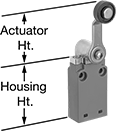
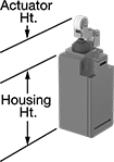
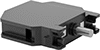
Low-Profile Limit Switches
 |  |  |
Style A | Style B | Style D |
 |  | |
Style E | Style G |
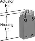
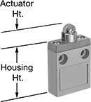
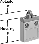
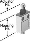
Stack these slim switches together, or fit them into tight spaces. They're rated IP67 for protection from temporary submersion. When an object in motion comes into contact with the actuator, it sends a signal to open or close a circuit. These switches have the rapid-closing action of a snap-acting switch, but have a larger actuator for large objects. They’re often used on conveyor systems and elevators.
Plunger Actuator—Plunger actuators open or close circuits when objects push against them.
Roller Plunger Actuator—Roller plunger actuators open or close circuits when an object pushes against the roller, which moves the plunger. The roller moves parallel to the mounting direction, so it helps push the plunger even if the force isn’t straight on. The roller also reduces friction during actuation which prevents wear and tear over time.
Cross Roller Plunger Actuator—Cross roller plunger actuators open or close circuits when an object pushes against the roller, which moves the plunger. The roller moves perpendicular to the mounting direction and reduces friction during actuation which prevents wear and tear over time.
Roller Lever Actuator—Roller lever actuators open or close circuits when material moves across the switch. The roller reduces friction during actuation which prevents wear and tear over time.
Wobble Stick Actuator—Wobble stick actuators open or close circuits when an object hits the flexible arm. The arm has a 360° range of motion, so it can be actuated from any direction. This means that if there’s a jam, these switches are less likely to break than switches that are aligned to a specific direction.
Housing | |||||||||||||||||||
|---|---|---|---|---|---|---|---|---|---|---|---|---|---|---|---|---|---|---|---|
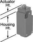
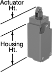
Style | No. of Circuits Controlled | Switch Starting Position | Switch Action | Switch Designation | Switching Current @ Voltage | Max. Voltage | Operating Temp. Range, ° F | Actuator Ht. | No. of Wire Leads | Cable Lead Lg., ft. | Lg. | Ht. | Dp. | Housing Material | Enclosure Rating | Each | |||
Plunger Actuator | |||||||||||||||||||
Wire Lead Connection | |||||||||||||||||||
| A | 1 | 1 Off or 1 On | Momentary | SPDT | 5 amp @ 250V AC, 4 amp @ 30V DC | 250V AC 250V DC | 14 to 158 | 0.2" | 4 | 9.5 | 1.6" | 1.9" | 0.6" | Aluminum | IP67 | 7628K73 | 0000000 | ||
Roller Plunger Actuator | |||||||||||||||||||
Wire Lead Connection | |||||||||||||||||||
| B | 1 | 1 Off or 1 On | Momentary | SPDT | 5 amp @ 250V AC, 4 amp @ 30V DC | 250V AC 250V DC | 14 to 158 | 0.6" | 4 | 9.5 | 1.6" | 2" | 0.6" | Aluminum | IP67 | 7628K74 | 000000 | ||
Cross Roller Plunger Actuator | |||||||||||||||||||
Wire Lead Connection | |||||||||||||||||||
| D | 1 | 1 Off or 1 On | Momentary | SPDT | 5 amp @ 250V AC, 4 amp @ 30V DC | 250V AC 250V DC | 14 to 158 | 0.6" | 4 | 9.5 | 1.6" | 2" | 0.6" | Aluminum | IP67 | 7628K75 | 000000 | ||
Roller Lever Actuator | |||||||||||||||||||
Wire Lead Connection | |||||||||||||||||||
| E | 1 | 1 Off or 1 On | Momentary | SPDT | 5 amp @ 250V AC, 4 amp @ 30V DC | 250V AC 250V DC | 14 to 158 | 2" | 4 | 9.5 | 1.6" | 2" | 0.6" | Aluminum | IP67 | 7628K77 | 000000 | ||
Wobble Stick Actuator | |||||||||||||||||||
Wire Lead Connection | |||||||||||||||||||
| G | 1 | 1 Off or 1 On | Momentary | SPDT | 5 amp @ 250V AC, 4 amp @ 30V DC | 250V AC 250V DC | 14 to 158 | 3.6" | 4 | 9.5 | 1.6" | 1.9" | 0.6" | Aluminum | IP67 | 7628K76 | 000000 | ||
Aluminum Enclosed Push-Button Switches
Screw-Terminal Wire Connection
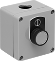 | 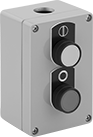 | 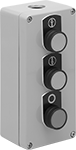 |
One Button | Two Buttons | Three Buttons |
 |  |
Circle | Vertical Line |
 |  |
Up Arrow | Down Arrow |
Actuator Color (Switch Designation) | No. of Circuits Controlled per Button | Switch Starting Position | Switch Action | No. of Terminals per Button | Switching Current @ Voltage | Max. Voltage | Conduit Trade Size | Enclosure Rating | Hazardous Location Rating | Each | |||
|---|---|---|---|---|---|---|---|---|---|---|---|---|---|
1 Button | |||||||||||||
| Green with Vertical Line (SPST-NO) | 1 | 1 Off | Momentary | 2 | 10 amp @ 120V AC, 4 amp @ 24V DC | 600V AC 600V DC | 1/2 | IP66, IP67, NEMA 4X, NEMA 13 | ATEX II 1 GD Ex Ia IIC T6-T3 Ga Ex Ta IIIC T85°C-T180°C Da; ATEX II 2 GD Ex E IIC T6-T3 Gb Ex Tb IIIC T85°C-T180°C Db; Ex E IIC; IEC Zone 0 Groups IIC, IIB, IIA; IEC Zone 20 Groups IIIC, IIIB, IIIA; IECEx Ex E IIC T6-T3 Gb Ex Tb IIIC T85°C-T180°C Db; IECEx Ex Ia IIC T6-T3 Ga Ex Ta IIIC T85°C-T180°C Da; NEC Class I Division 2 Groups A, B, C, D; NEC Zone 1 Groups IIC, IIB, IIA | 6156K41 | 0000000 | ||
| Red with Circle (SPST-NC) | 1 | 1 On | Momentary | 2 | 10 amp @ 120V AC, 4 amp @ 24V DC | 600V AC 600V DC | 1/2 | IP66, IP67, NEMA 4X, NEMA 13 | ATEX II 1 GD Ex Ia IIC T6-T3 Ga Ex Ta IIIC T85°C-T180°C Da; ATEX II 2 GD Ex E IIC T6-T3 Gb Ex Tb IIIC T85°C-T180°C Db; Ex E IIC; IEC Zone 0 Groups IIC, IIB, IIA; IEC Zone 20 Groups IIIC, IIIB, IIIA; IECEx Ex E IIC T6-T3 Gb Ex Tb IIIC T85°C-T180°C Db; IECEx Ex Ia IIC T6-T3 Ga Ex Ta IIIC T85°C-T180°C Da; NEC Class I Division 2 Groups A, B, C, D; NEC Zone 1 Groups IIC, IIB, IIA | 6156K42 | 000000 | ||
2 Buttons | |||||||||||||
| Green with Vertical Line (SPST-NO) Red with Circle (SPST-NC) | 1 | 1 Off | Momentary | 2 | 10 amp @ 120V AC, 4 amp @ 24V DC | 600V AC 600V DC | 1/2 | IP66, IP67, NEMA 4X, NEMA 13 | ATEX II 1 GD Ex Ia IIC T6-T3 Ga Ex Ta IIIC T85°C-T180°C Da; ATEX II 2 GD Ex E IIC T6-T3 Gb Ex Tb IIIC T85°C-T180°C Db; Ex E IIC; IEC Zone 0 Groups IIC, IIB, IIA; IEC Zone 20 Groups IIIC, IIIB, IIIA; IECEx Ex E IIC T6-T3 Gb Ex Tb IIIC T85°C-T180°C Db; IECEx Ex Ia IIC T6-T3 Ga Ex Ta IIIC T85°C-T180°C Da; NEC Class I Division 2 Groups A, B, C, D; NEC Zone 1 Groups IIC, IIB, IIA | 6156K45 | 000000 | ||
3 Buttons | |||||||||||||
| Green with Up Arrow (SPST-NO) Red with Circle (SPST-NC) Green with Down Arrow (SPST-NO) | 1 | 1 Off | Momentary | 2 | 10 amp @ 120V AC, 4 amp @ 24V DC | 600V AC 600V DC | 1/2 | IP66, IP67, NEMA 4X, NEMA 13 | ATEX II 1 GD Ex Ia IIC T6-T3 Ga Ex Ta IIIC T85°C-T180°C Da; ATEX II 2 GD Ex E IIC T6-T3 Gb Ex Tb IIIC T85°C-T180°C Db; Ex E IIC; IEC Zone 0 Groups IIC, IIB, IIA; IEC Zone 20 Groups IIIC, IIIB, IIIA; IECEx Ex E IIC T6-T3 Gb Ex Tb IIIC T85°C-T180°C Db; IECEx Ex Ia IIC T6-T3 Ga Ex Ta IIIC T85°C-T180°C Da; NEC Class I Division 2 Groups A, B, C, D; NEC Zone 1 Groups IIC, IIB, IIA | 6156K46 | 000000 | ||
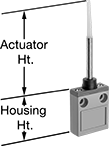
Sealed Low-Profile Limit Switches
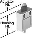 |  |  |
Style B | Style C | Style D |
A sealed actuator prevents these switches from jamming, even when exposed to sand, mud, or dirt. They're also rated IP67 for temporary submersion. With a slim design, you can stack them or fit them in tight spaces. When an object in motion comes into contact with the actuator, it sends a signal to open or close a circuit. These switches have the rapid-closing action of a snap-acting switch, but with a larger actuator. This makes them a good choice for use with large objects. For instance, a box on a conveyor runs into the switch, stopping the conveyor.
Plunger Actuator—Switches with a plunger actuator require a push to actuate, similar to a button.
Roller Plunger Actuator—Switches with a roller plunger actuator have a roller that moves when an object pushes the actuator. This reduces friction during actuation to limit wear and tear on your switch.
Cross Roller Plunger Actuator—Switches with a cross roller plunger actuator have a roller that moves when an object pushes the actuator. This reduces friction during actuation to limit wear and tear on your switch. The roller moves perpendicular to the mounting direction.
Housing | |||||||||||||||||||
|---|---|---|---|---|---|---|---|---|---|---|---|---|---|---|---|---|---|---|---|
Style | No. of Circuits Controlled | Switch Starting Position | Switch Action | Switch Designation | Switching Current @ Voltage | Max. Voltage | Operating Temp. Range, ° F | Actuator Ht. | No. of Wire Leads | Cable Lead Lg., ft. | Lg. | Ht. | Dp. | Housing Material | Enclosure Rating | Each | |||
Plunger Actuator | |||||||||||||||||||
Wire Lead Connection | |||||||||||||||||||
| B | 1 | 1 Off or 1 On | Momentary | SPDT | 5 amp @ 250V AC, 4 amp @ 30V DC | 250V AC 250V DC | 14 to 158 | 0.6" | 4 | 9.5 | 1.3" | 1.9" | 0.6" | Aluminum | IP67 | 7317K11 | 0000000 | ||
Roller Plunger Actuator | |||||||||||||||||||
Wire Lead Connection | |||||||||||||||||||
| C | 1 | 1 Off or 1 On | Momentary | SPDT | 5 amp @ 250V AC, 4 amp @ 30V DC | 250V AC 250V DC | 14 to 158 | 1" | 4 | 9.5 | 1.6" | 1.9" | 0.6" | Aluminum | IP67 | 7317K12 | 000000 | ||
Cross Roller Plunger Actuator | |||||||||||||||||||
Wire Lead Connection | |||||||||||||||||||
| D | 1 | 1 Off or 1 On | Momentary | SPDT | 5 amp @ 250V AC, 4 amp @ 30V DC | 250V AC 250V DC | 14 to 158 | 1" | 4 | 9.5 | 1.3" | 1.9" | 0.6" | Aluminum | IP67 | 7317K13 | 000000 | ||
Frame-Mounted Safety Switches
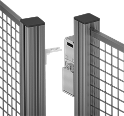 |
Key Shown Actuating from the Side |
 |  | |
Style A | Style C | Style G |
Also known as interlock switches, these ensure the safety of personnel by automatically shutting off power to machinery when an access door opens. Mount the switch to the door frame and mount a key to the door so that the key is inserted into the switch when the door is closed. When the door opens, the key is removed from the switch and the machine shuts down. They’re often used with machine guards for large robots.
For the Manufacturer User Manual, click on a part number and select Product Detail.
Styles A-G—Style A-G switches have positive-force, normally closed contacts that will open a circuit when the switch is actuated even if a spring fails or the contacts stick.
IP67 Enclosure Rating—IP67 rated switches protect against temporary submersion.
Key Included—All switches require an actuator key, but not all include one—check whether you need to pick out a separate actuator key. For some switch styles, you can also select the mounting orientation of the key.
Housing | Conduit | ||||||||||||||||||
|---|---|---|---|---|---|---|---|---|---|---|---|---|---|---|---|---|---|---|---|
Style | No. of Circuits Controlled | Switch Starting Position | Switch Action | No. of Terminals | Switch Designation | Switching Current @ Voltage | Max. Voltage | Ht. | Wd. | Dp. | Trade Size | Thread Size | Thread Type | Key Included | Enclosure Rating | Each | |||
Wire Lead Connection with Positive-Force Normally Closed Contacts | |||||||||||||||||||
| A | 2 | 1 Off and 1 On | Maintained | 2 | DPST-1NO/1NC | 8 amp @ 120V AC, 4 amp @ 24V DC | 250V AC 24V DC | 3.3" | 1.2" | 1.2" | — | M16 | Metric | Yes | IP67 | 65665K25 | 0000000 | ||
Screw-Terminal Wire Connection with Positive-Force Normally Closed Contacts | |||||||||||||||||||
| C | 3 | 1 Off and 2 On | Maintained | 3 | 3PST-1NO/2NC | 8 amp @ 120V AC, 4 amp @ 24V DC | 600V AC 250V DC | 3.5" | 2.1" | 1.2" | 1/2 | — | NPT | Yes | IP67 | 65665K15 | 000000 | ||
| C | 3 | 1 Off and 2 On | Maintained | 6 | 3PST-1NO/2NC | 4 amp @ 230V AC, 4 amp @ 24V DC | 500V AC 24V DC | 3.5" | 2" | 1.2" | — | M16 | Metric | Yes | IP67 | 65665K18 | 000000 | ||
Screw-Terminal Wire Connection with Positive-Force Normally Closed Contacts and Rotating Head | |||||||||||||||||||
| G | 3 | 1 Off and 2 On | Maintained | 6 | 3PST-1NO/2NC | 10 amp @ 230V AC, 4 amp @ 24V DC | 250V AC 24V DC | 4.3" | 1.6" | 1.4" | — | M20 | Metric | No | IP67 | 65665K19 | 000000 | ||
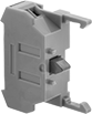
Switch Contact Blocks
 |
Make or break an electrical circuit. These contact blocks mount to manual switches and transmit an electrical signal when the switch actuator is engaged. You can stack multiple blocks, so a single switch can control several circuits. This is helpful in setups that require multiple systems to turn on or off at the same time. For example, the switch on a conveyor line could turn off the conveyor and turn on a diverter and alarm.
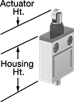
Compact Safety Limit Switches
 |  |  |
Style A | Style B | Style C |
Shorter and thinner than other safety limit switches, these are sized to fit tight spaces. They protect machinery and ensure the safety of personnel. Positive-force contacts open the circuit when actuated, even if a spring fails or the contacts stick. They send a signal to your circuit when an object hits the actuator—for instance, a box on a conveyor runs into the switch, stopping the conveyor. They open and close circuits as fast as snap-acting switches, but they have a bigger actuator for large objects. All are NEMA and IP rated for protection from washdowns.
Plunger Actuator—Switches with a plunger actuator require a push to actuate, similar to a button.
Roller Plunger Actuator—Switches with a roller plunger actuator have a roller that moves parallel to the mounting direction when an object pushes the actuator. This reduces friction during actuation to limit wear and tear on your switch.
Roller Lever Actuator—Switches with a roller lever actuator use a lever with a roller at the end to activate. This allows parts to glide across the actuation surface with minimal friction, limiting wear and tear.
Housing | |||||||||||||||||||
|---|---|---|---|---|---|---|---|---|---|---|---|---|---|---|---|---|---|---|---|
Style | No. of Circuits Controlled | Switch Starting Position | Switch Action | Switch Designation | Switching Current @ Voltage | Max. Voltage | Operating Temp. Range, ° F | Actuator Ht. | No. of Terminals | Lg. | Ht. | Dp. | Housing Material | Conduit Thread Size | Enclosure Rating | Each | |||
Plunger Actuator | |||||||||||||||||||
Screw-Terminal Wire Connection | |||||||||||||||||||
| A | 1 | 1 Off or 1 On | Momentary | SPDT | 10 amp @ 240V AC, 4 amp @ 24V DC | 240V AC 24V DC | -22 to 176 | 0.5" | 4 | 1.2" | 2.4" | 1.2" | Plastic | M20 | NEMA 4, IP65 | 65745K51 | 0000000 | ||
Roller Plunger Actuator | |||||||||||||||||||
Screw-Terminal Wire Connection | |||||||||||||||||||
| B | 1 | 1 Off or 1 On | Momentary | SPDT | 10 amp @ 240V AC, 4 amp @ 24V DC | 240V AC 24V DC | -22 to 176 | 1.2" | 4 | 1.2" | 2.4" | 1.2" | Plastic | M20 | NEMA 4, IP65 | 65745K52 | 000000 | ||
Roller Lever Actuator | |||||||||||||||||||
Screw-Terminal Wire Connection | |||||||||||||||||||
| C | 1 | 1 Off or 1 On | Momentary | SPDT | 10 amp @ 240V AC, 4 amp @ 24V DC | 240V AC 24V DC | -22 to 176 | 1.1" | 4 | 1.2" | 2.4" | 1.2" | Plastic | M20 | NEMA 4, IP65 | 65745K53 | 000000 | ||
Hazardous Location 30 mm Panel-Mount Key Switches
 |
Designed for use near ignitable gases, fibers, and dust, these switches have a housing that seals in anything that could ignite flammable material. You’ll know they’re safe because they’re NEC Class 1, Division 2 Groups A-D and NEC Zone 1 Groups IIC-IIA certified for hazardous locations. These switches require a key to turn circuits on or off, preventing accidental actuation and limiting access to sensitive equipment. Since they’re keyed alike, all open with the same key. Install them in a standard panel cutout.
2 Circuits Controlled—Switches that control two circuits come with a contact block for each circuit.
No. of Circuits Controlled | Switch Starting Position | Switch Action | No. of Terminals | Switch Designation | Switching Current @ Voltage | Max. Voltage | Dia. | Dp. Behind Panel | For Max. No. of Contact Blocks | No. of Keys Included | Key Removal Position | Enclosure Rating | Each | |||
|---|---|---|---|---|---|---|---|---|---|---|---|---|---|---|---|---|
2 Positions with Plastic Actuator Base | ||||||||||||||||
Keyed Alike with Screw-Terminal Wire Connection | ||||||||||||||||
| 1 | 1 Off | Momentary | 2 | SPST-NO | 6 amp @ 120V AC, 4 amp @ 24V DC | 500V AC 500V DC | 1 9/16" | 2 5/8" | 3 | 2 | Left | IP20 | 6914N13 | 0000000 | ||
| 1 | 1 Off | Maintained | 2 | SPST-NO | 6 amp @ 120V AC, 4 amp @ 24V DC | 500V AC 500V DC | 1 9/16" | 2 5/8" | 3 | 2 | Left, Right | IP20 | 6914N11 | 000000 | ||
| 1 | 1 On | Maintained | 2 | SPST-NC | 6 amp @ 120V AC, 4 amp @ 24V DC | 500V AC 500V DC | 1 9/16" | 2 5/8" | 3 | 2 | Left, Right | IP20 | 6914N12 | 000000 | ||
| 2 | 1 Off and 1 On | Maintained | 4 | DPST-1NO/1NC | 6 amp @ 120V AC, 4 amp @ 24V DC | 500V AC 500V DC | 1 9/16" | 2 5/8" | 3 | 2 | Left, Right | IP20 | 6914N14 | 000000 | ||
3 Positions with Plastic Actuator Base | ||||||||||||||||
Keyed Alike with Screw-Terminal Wire Connection | ||||||||||||||||
| 2 | 2 Off | Maintained | 4 | DPST-NO | 6 amp @ 120V AC, 4 amp @ 24V DC | 500V AC 500V DC | 1 9/16" | 2 5/8" | 3 | 2 | Center, Left, Right | IP20 | 6914N15 | 000000 | ||
 |
Additional contact blocks can be added to control more circuits, or to replace the included contact block.
 |
Key No. | Each | ||
|---|---|---|---|
| HW9Z-SKP | 6914N16 | 000000 |
Handle Push-Button Switches
Style A
Status Indicators—Switches with status indicators alert you when a switch has been actuated.
Handles without Switch—Add a matching handle without a switch to keep door pulls uniform.
Push-Button Switches | Handles without Switch | ||||||||||||||
|---|---|---|---|---|---|---|---|---|---|---|---|---|---|---|---|
No. of Circuits Controlled | Switch Starting Position | Switch Action | Actuator Color (Switch Designation) | No. of Terminals | Switching Current @ Voltage | Max. Voltage | Handle Lg. | No. of Poles | Electrical Connection | Each | Each | ||||
Glass-Filled Nylon Handle—Status Indicators | |||||||||||||||
| 1 | 1 Off | Maintained | Purple (SPST-NO) | 2 | 4 amp @ 12V DC | 48V DC | 6 5/16" | 8 | M12 | 7095N13 | 0000000 | 7095N12 | 000000 | ||
| 2 | 1 Off and 1 On | Momentary | Blue (DPST-1NO/1NC) | 4 | 1 amp @ 115V AC, 4 amp @ 28V DC | 115V AC 28V DC | 6 5/16" | 8 | M12 | 7095N11 | 000000 | 7095N12 | 00000 | ||
Washdown 3/4" Panel-Mount Key Switches
 |
Tab Wire Connection |
Rated NEMA 4 or IP66, these switches are protected from washdowns. They require a key to turn circuits on or off, limiting access to sensitive equipment. All fit into a standard panel cutout.
Keyed Alike—Keyed alike switches all open with the same key.
Keyed Differently—Keyed differently switches each open with a unique key.
Key Switches | Replacement Keys | ||||||||||||||||
|---|---|---|---|---|---|---|---|---|---|---|---|---|---|---|---|---|---|
No. of Circuits Controlled | Switch Starting Position | Switch Action | No. of Terminals | Switch Designation | Switching Current @ Voltage | Max. Voltage | Dia. | Dp. Behind Panel | No. of Keys Included | Key Removal Position | Enclosure Rating | Each | Each | ||||
2 Positions with Metal Actuator Base | |||||||||||||||||
Keyed Alike with Tab Wire Connection | |||||||||||||||||
| 1 | 1 Off or 1 On | Maintained | 3 | SPDT | 4 amp @ 125V AC/28V DC | 125V AC 28V DC | 7/8" | 1 1/4" | 2 | Center, Right | NEMA 4, IP66 | 7182K11 | 000000 | 7182K2 | 00000 | ||
Keyed Differently with Tab Wire Connection | |||||||||||||||||
| 1 | 1 Off or 1 On | Maintained | 3 | SPDT | 4 amp @ 125V AC/28V DC | 125V AC 28V DC | 7/8" | 1 1/4" | 2 | Center, Right | NEMA 4, IP66 | 7182K12 | 00000 | ——— | 0 | ||
Miniature 15/32" Panel-Mount Key Switches
 |
Maximize space in a panel with these miniature switches. They require a key to turn circuits on or off, limiting access to sensitive equipment. All are keyed alike, so they open with the same key.
Wire Leads | ||||||||||||||||
|---|---|---|---|---|---|---|---|---|---|---|---|---|---|---|---|---|
No. of Circuits Controlled | Switch Starting Position | Switch Action | No. of Terminals | Switch Designation | Switching Current @ Voltage | Max. Voltage | Dia. | Dp. Behind Panel | No. of | Lg. | No. of Keys Included | Key Removal Position | Each | |||
2 Positions with Metal Actuator Base | ||||||||||||||||
Keyed Alike with Wire Lead Connection | ||||||||||||||||
| 1 | 1 Off | Maintained | 2 | SPST-NO | 4 amp @ 125V AC/24V DC | 250V AC 28V DC | 9/16" | 1 5/16" | 2 | 6" | 2 | Center | 65635K14 | 000000 | ||
Build-Your-Own Limit Switches
Switches
4-Pole M12 Connection |
Polypropylene Housing—Switches with a polypropylene housing are lighter in weight than metal switches.
4-Pole M12 Connection—Switches with a 4-pole M12 plug quickly connect and disconnect from your setup. Use cords (sold separately) to wire your switch connection to your setup.
IP65 Enclosure Rating—IP65 switches protect against dust and splashing water.
IP67 Enclosure Rating—IP67 switches protect against dust and temporary submersion.
Switches | Cords | ||||||||||||||||
|---|---|---|---|---|---|---|---|---|---|---|---|---|---|---|---|---|---|
Housing | |||||||||||||||||
No. of Circuits Controlled | Switch Starting Position | Switch Action | Switch Designation | Switching Current @ Voltage | Max. Voltage | Lg. | Ht. | Dp. | Enclosure Rating | Specs. Met | Certification | Each | Each | ||||
Polypropylene Housing | |||||||||||||||||
4-Pole M12 Connection | |||||||||||||||||
| 2 | 1 Off and 1 On | Momentary | DPST-1NO/1NC | 4 amp @ 240V AC, 3 amp @ 24V DC | 250V AC 250V DC | 1.2" | 2.7" | 1.3" | IP65 | EN 50047 | UL Listed, C-UL Listed, CE Marked, CCC Marked | 7976N12 | 0000000 | 7628K99 | 000000 | ||
| 2 | 1 Off and 1 On | Momentary | DPST-1NO/1NC | 4 amp @ 240V AC, 3 amp @ 24V DC | 250V AC 250V DC | 1.6" | 3.1" | 1.5" | IP67 | EN 50041 | UL Listed, C-UL Listed, CE Marked, CCC Marked | 7976N23 | 000000 | 7628K99 | 00000 | ||
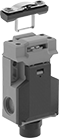
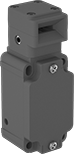
Access-Delay Frame-Mounted Safety Switches
| 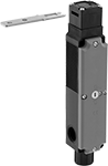 |
Key Shown Actuating from the Side | Style C |
Delay access to hazardous areas until conditions are safe; use these switches with machines that take time to stop after they are turned off. Mount the switch to the door frame and mount the key to the door so that the key is inserted into the switch when the door is closed. When the door is pulled, the key is held in place with 225 lbs. of force until the switch receives a signal from a time-delay relay, motion sensor, or position sensor (not included) that the machine’s motion has stopped. After the motion has stopped, the key can be removed from the switch, releasing the access door. They’re often used with machine guards. All have positive-force, normally-closed contacts that will open a circuit when the switch is actuated even if a spring fails or the contacts stick. They’re rated for protection from washdowns and temporary submersion.
For the Manufacturer User Manual, click on a part number and select Product Detail.
Style C—Style C has a key entry on two opposite sides of the switch.
Housing | Conduit | ||||||||||||||||||
|---|---|---|---|---|---|---|---|---|---|---|---|---|---|---|---|---|---|---|---|
Style | No. of Circuits Controlled | Switch Starting Position | Switch Action | No. of Terminals | Switch Designation | Switching Current @ Voltage | Max. Voltage | Input Voltage | Holding Force, lbf | Ht. | Wd. | Dp. | Trade Size | Thread Type | Enclosure Rating | Each | |||
Screw-Terminal Wire Connection with Positive-Force Normally Closed Contacts and Rotating Head | |||||||||||||||||||
| C | 4 | 2 Off and 2 On | Maintained | 8 | 4PST-2NO/2NC | 4 amp @ 120V AC, 4 amp @ 24V DC | 240V AC 24V DC | 24V AC, 24V DC | 225 | 7.6" | 1.2" | 1.6" | 1/2 | NPT | IP67 | 7787K12 | 0000000 | ||
Safety Relays with Diagnostic Capabilities
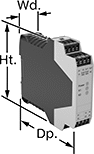 |
Relay |
Control and diagnose issues with safety-critical circuits. These relays have a microprocessor that monitors safety components, such as emergency stops and light curtains, and sends a signal to stop the operation if a failure is detected and restart when the issue is resolved. They also help with diagnostic tasks because of their feedback circuit, which allows basic relays to communicate their status back to the safety relay. These relays have a duplicate set of input and output signals, so they’ll still stop the controlled device if one of the inputs fails.
IP20 rated, they have recessed terminals which prevent fingers and other objects from touching live circuits. These relays have been tested to multiple safety standards and can help achieve PL, SIL, or CAT system ratings. They also meet ISO and IEC standards for machine safety.
Mount them to 35 mm DIN rail (also known as DIN 3 Rail) for fast installation.
No. of Terminals | Input Voltage | Switching Current @ Voltage | Max. Switching Voltage, V AC | Ht. | Wd. | Dp. | For Use With | Mounting Location | Max. System Safety Rating | Each | |||
|---|---|---|---|---|---|---|---|---|---|---|---|---|---|
3 Circuits Controlled | |||||||||||||
3 Safety Outputs with 2 Off and 1 Signal Output with 2 On | |||||||||||||
| 16 | 24V DC | 4 amp @ 230V AC 4 amp @ 24V DC | 240 | 3.9" | 0.9" | 4.5" | Emergency Stops | DIN Rail | PLe, SIL 3 | 6322N19 | 0000000 | ||
 | 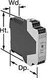 |
Auxiliary Contact Block | Auxiliary Contact Block with Time Delay |
No. of Terminals | Input Voltage, V DC | Switching Current @ Voltage | Max. Switching Voltage | Ht. | Wd. | Dp. | Features | Each | |||
|---|---|---|---|---|---|---|---|---|---|---|---|
5 Safety Outputs | |||||||||||
| 16 | 24 | 3 amp @ 240V AC 2.5 amp @ 24V DC | 250V AC, 250V DC | 3.9" | 0.9" | 4.5" | — | 6322N22 | 0000000 | ||
4 Delayed Safety Outputs | |||||||||||
| 16 | 24 | 3 amp @ 240V AC 3 amp @ 24V DC | 250V AC, 250V DC | 3.9" | 0.9" | 4.5" | Time Delay | 6322N18 | 000000 | ||
