Filter by
Position Designation
Switching Voltage
Switch Action
Actuator Style


Switching Current
Wire Connection
Input Voltage
Switch Starting Position
Electrical Connection
Illumination
Toggle Type
DFARS Specialty Metals
Export Control Classification Number (ECCN)

About Electrical Switches
Choose a switch with the right trigger type, number of inputs, and control functions to power your equipment.
Mil. Spec. Washdown Toggle Switches
 |
These switches meet MIL-S-3950. A rubber seal protects them from washdowns.
No. of Circuits Controlled | Switch Starting Position | Switch Action | No. of Terminals | Switch Designation | Position Designation | Switching Current @ Voltage | Max. Voltage | Dp. Behind Panel | Mounting Hardware Included | Wire Connection | Each | |||
|---|---|---|---|---|---|---|---|---|---|---|---|---|---|---|
2 Positions | ||||||||||||||
For 1/2" Diameter Panel Cutouts | ||||||||||||||
| 1 | 1 Off | Momentary | 2 | SPST | Off-(On) | 7 amp @ 125V AC, 10 amp @ 28V DC | 28V DC 125V AC | 1.16" | Yes | Screw Terminal | 8002K123 | 000000 | ||
| 1 | 1 Off or 1 On | Momentary | 3 | SPDT | On-(On) | 7 amp @ 125V AC, 10 amp @ 28V DC | 28V DC 125V AC | 1.16" | Yes | Screw Terminal | 8002K124 | 00000 | ||
| 1 | 1 On | Momentary | 2 | SPST | On-(Off) | 7 amp @ 125V AC, 10 amp @ 28V DC | 28V DC 125V AC | 1.16" | Yes | Screw Terminal | 8002K121 | 00000 | ||
3 Positions | ||||||||||||||
For 1/2" Diameter Panel Cutouts | ||||||||||||||
| 1 | 1 Off or 1 On | Momentary | 3 | SPDT | (On)-Off-On | 7 amp @ 125V AC, 10 amp @ 28V DC | 28V DC 125V AC | 1.16" | Yes | Screw Terminal | 8002K122 | 00000 | ||
| 1 | 1 Off or 1 On | Momentary | 3 | SPDT | (On)-Off-(On) | 7 amp @ 125V AC, 10 amp @ 28V DC | 28V DC 125V AC | 1.16" | Yes | Screw Terminal | 8002K116 | 00000 | ||
Light Beam Finger-Touch Switches
 |
An infrared light beam senses the lightest finger contact to switch a circuit on or off. The included guard prevents accidental activation. An indicator lights up to confirm that switches are actuated. They’re rated NEMA 4X, 13, and IP66 for protection from corrosion, washdowns, and oil/coolant spraying.
M22 Connection—Switches with a 5-pole M22 connection can quickly be changed out.
Wire Leads | ||||||||||||||
|---|---|---|---|---|---|---|---|---|---|---|---|---|---|---|
No. of Circuits Controlled | Switch Starting Position | Switch Action | Switch Designation | Actuator Color | Switching Current @ Voltage | Input Voltage | Dp. Behind Panel | No. of | Ga. | Features | Each | |||
Plastic Actuator with Wire Lead Connection | ||||||||||||||
For 30 mm (1 3/16") Diameter Panel Cutouts | ||||||||||||||
| 1 | 1 Off or 1 On | Momentary | SPDT | Black | 7 amp @ 120V AC | 120V AC | 3/4" | 5 | 22 | Guard Output Indicator Power Indicator | 72025K91 | 0000000 | ||
| 1 | 1 Off or 1 On | Momentary | SPDT | Black | 7 amp @ 120V AC | 20V AC to 30V AC/20V DC to 30V DC | 3/4" | 5 | 22 | Guard Output Indicator Power Indicator | 72025K93 | 000000 | ||
Plastic Actuator with 5-Pole M22 Connection | ||||||||||||||
For 30 mm (1 3/16") Diameter Panel Cutouts | ||||||||||||||
| 1 | 1 Off or 1 On | Momentary | SPDT | Black | 7 amp @ 120V AC | 120V AC | 1 3/8" | — | — | Guard Output Indicator Power Indicator | 72025K92 | 000000 | ||
| 1 | 1 Off or 1 On | Momentary | SPDT | Black | 7 amp @ 120V AC | 20V AC to 30V AC/20V DC to 30V DC | 1 3/8" | — | — | Guard Output Indicator Power Indicator | 72025K11 | 000000 | ||
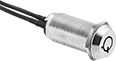
3/4" Panel-Mount Key Switches
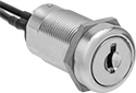 |
Wire Lead Connection |
Prevent accidental activation and limit access—these switches require a key to turn circuits on or off. All fit into a standard panel cutout.
Keyed Alike—Keyed alike switches all open with the same key.
Keyed Differently—Keyed differently switches each open with a unique key.
Master Keyed—Keyed differently/master keyed switches are keyed differently but can be used with a master key (sold separately).
Key Switches | Replacement Keys | Master Keys | ||||||||||||||||||
|---|---|---|---|---|---|---|---|---|---|---|---|---|---|---|---|---|---|---|---|---|
Wire Leads | ||||||||||||||||||||
No. of Circuits Controlled | Switch Starting Position | Switch Action | No. of Terminals | Switch Designation | Switching Current @ Voltage | Max. Voltage | Dia. | Dp. Behind Panel | No. of | Lg. | No. of Keys Included | Key Removal Position | Each | Each | Each | |||||
2 Positions with Metal Actuator Base | ||||||||||||||||||||
Keyed Alike with Wire Lead Connection | ||||||||||||||||||||
| 1 | 1 Off | Momentary | 2 | SPST-NO | 7 amp @ 28V AC/28V DC | 28V AC 28V DC | 7/8" | 1 1/8" | 2 | 10" | 2 | Center | 7188K101 | 000000 | 7188K104 | 00000 | ——— | 0 | ||
| 1 | 1 Off | Maintained | 2 | SPST-NO | 7 amp @ 28V AC/28V DC | 28V AC 28V DC | 7/8" | 1 1/8" | 2 | 10" | 2 | Center, Right | 7188K22 | 00000 | 7188K62 | 0000 | ——— | 0 | ||
Keyed Differently with Wire Lead Connection | ||||||||||||||||||||
| 1 | 1 Off | Momentary | 2 | SPST-NO | 7 amp @ 28V AC/28V DC | 28V AC 28V DC | 7/8" | 1 1/8" | 2 | 10" | 2 | Center | 7188K102 | 00000 | 7188K105 | 0000 | ——— | 0 | ||
| 1 | 1 Off | Maintained | 2 | SPST-NO | 7 amp @ 28V AC/28V DC | 28V AC 28V DC | 7/8" | 1 1/8" | 2 | 10" | 2 | Center, Right | 7188K21 | 00000 | 7188K61 | 0000 | ——— | 0 | ||
Keyed Differently/Master Keyed with Wire Lead Connection | ||||||||||||||||||||
| 1 | 1 Off | Momentary | 2 | SPST-NO | 7 amp @ 28V AC/28V DC | 28V AC 28V DC | 7/8" | 1 1/8" | 2 | 10" | 2 | Center | 7188K103 | 00000 | ——— | 0 | 7188K106 | 00000 | ||
| 1 | 1 Off | Maintained | 2 | SPST-NO | 7 amp @ 28V AC/28V DC | 28V AC 28V DC | 7/8" | 1 1/8" | 2 | 10" | 2 | Center, Right | 7188K23 | 00000 | ——— | 0 | 7188K14 | 0000 | ||
High-Security 3/4" Panel-Mount Key Switches
 |
With a round key that is difficult to duplicate, these switches provide a higher degree of security than standard key switches.
Keyed Alike—Keyed alike switches all open with the same key.
Keyed Differently—Keyed differently switches each open with a unique key.
Master Keyed—Keyed differently/master keyed switches are keyed differently but can be used with a master key (sold separately).
Key Switches | Replacement Keys | |||||||||||||||||
|---|---|---|---|---|---|---|---|---|---|---|---|---|---|---|---|---|---|---|
Wire Leads | ||||||||||||||||||
No. of Circuits Controlled | Switch Starting Position | Switch Action | No. of Terminals | Switch Designation | Switching Current @ Voltage | Max. Voltage | Dia. | Dp. Behind Panel | No. of | Lg. | No. of Keys Included | Key Removal Position | Each | Each | ||||
2 Positions with Metal Actuator Base | ||||||||||||||||||
Keyed Alike with Wire Lead Connection | ||||||||||||||||||
| 1 | 1 Off | Maintained | 2 | SPST-NO | 7 amp @ 28V AC/28V DC | 28V AC 28V DC | 7/8" | 1 3/16" | 2 | 10" | 2 | Center, Right | 7188K26 | 000000 | 7188K31 | 000000 | ||
Keyed Differently with Wire Lead Connection | ||||||||||||||||||
| 1 | 1 Off | Maintained | 2 | SPST-NO | 7 amp @ 28V AC/28V DC | 28V AC 28V DC | 7/8" | 1 3/16" | 2 | 10" | 2 | Center, Right | 7188K25 | 00000 | 7188K51 | 00000 | ||
Keyed Differently/Master Keyed with Wire Lead Connection | ||||||||||||||||||
| 1 | 1 Off | Maintained | 2 | SPST-NO | 7 amp @ 28V AC/28V DC | 28V AC 28V DC | 7/8" | 1 3/16" | 2 | 10" | 2 | Center, Right | 7188K27 | 00000 | ——— | 0 | ||
Easy-Grip Pendant Switches
 |
Style F |
With a slim shape, these switches fit comfortably in your hand. Use them with mobile machinery such as cranes, hoists, and trolleys.
Style F
|
No. of Buttons | No. of Circuits Controlled per Actuator | Switch Starting Position | Switch Action | No. of Terminals per Actuator | Switching Current @ Voltage | Max. Voltage | Message (Actuator Color—Switch Designation) | Enclosure Rating | Each | |||
|---|---|---|---|---|---|---|---|---|---|---|---|---|
1 Speed with Screw Terminals | ||||||||||||
Yellow Plastic Housing | ||||||||||||
| 2 | 1 | 1 Off or 1 On | Momentary | 2 | 10 amp @ 120V AC 7 amp @ 24V DC | 250V AC 28V DC | 35 Assorted Labels (Black—SPDT) | IP67 | 7987K32 | 0000000 | ||
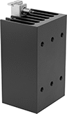
DIN-Rail Mount Interface Relays
4 Circuits Controlled with 4 Off or 4 On—4PDT
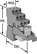 | 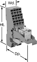 |
With Screw Terminals | With Spring-Clamp Terminals |
Interface Relays | Replacement Relays | ||||||||||||||
|---|---|---|---|---|---|---|---|---|---|---|---|---|---|---|---|
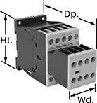
No. of Terminals | Input Voltage | Control Current, mA | Switching Current @ Voltage | Max. Switching Voltage, V AC | hp @ Switching Voltage | Ht. | Wd. | Dp. | Features | Each | Each | ||||
With Screw Terminals | |||||||||||||||
| 14 | 24V AC | 53 | 7 amp @ 240V AC | 250 | 1/8 hp @ 120V AC | 3.1" | 1.1" | 3.3" | LED Indicator, PLC Output Protection | 4144N109 | 000000 | 4144N124 | 000000 | ||
| 14 | 120V AC | 12 | 7 amp @ 240V AC | 250 | 1/8 hp @ 120V AC | 3.1" | 1.1" | 3.3" | LED Indicator, PLC Output Protection | 4144N111 | 00000 | 4144N125 | 00000 | ||
| 14 | 12V DC | 86 | 7 amp @ 240V AC | 250 | 1/8 hp @ 120V AC | 3.1" | 1.1" | 3.3" | LED Indicator, PLC Output Protection | 4144N113 | 00000 | 4144N127 | 00000 | ||
| 14 | 24V DC | 40 | 7 amp @ 240V AC | 250 | 1/8 hp @ 120V AC | 3.1" | 1.1" | 3.3" | LED Indicator, PLC Output Protection | 4144N112 | 00000 | 4144N126 | 00000 | ||
With Spring-Clamp Terminals | |||||||||||||||
| 14 | 24V AC | 53 | 7 amp @ 240V AC | 250 | 1/8 hp @ 120V AC | 3.9" | 1.2" | 3.3" | LED Indicator, PLC Output Protection | 4144N118 | 00000 | 4144N124 | 00000 | ||
| 14 | 12V DC | 86 | 7 amp @ 240V AC | 250 | 1/8 hp @ 120V AC | 3.9" | 1.2" | 3.3" | LED Indicator, PLC Output Protection | 4144N121 | 00000 | 4144N127 | 00000 | ||
| 14 | 24V DC | 40 | 7 amp @ 240V AC | 250 | 1/8 hp @ 120V AC | 3.9" | 1.2" | 3.3" | LED Indicator, PLC Output Protection | 4144N119 | 00000 | 4144N126 | 00000 | ||
Solid State Screw Terminal Relays
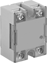 | 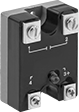 | 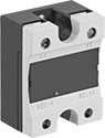 |
1-Circuit Relay with Covered Terminals and LED Indicator | 1-Circuit Relay with LED Indicator | 1-Circuit Relay with Covered Terminals |
 |  | |
1-Circuit Relay | Heat Sinks |
With no moving parts, these solid-state relays are fast switching and require less maintenance, last longer, and are quieter than mechanical switches.
Relays with High-Starting-Current Protection—Relays with high-starting-current protection are designed with integrated circuits that prevent damage from the large burst of electricity when a device, such as a motor or pump, turns on.
LED Indicator—Relays with LED indicator let you quickly spot whether a relay is on or off.
Heat Sinks—Heat sinks disperse heat to increase the relay’s current rating. Mount them to 35 mm DIN rail (also known as DIN 3 rail) for fast installation. They also mount to flat surfaces. Before mounting one-circuit relays, silicone compound or a thermal pad should be placed between the heat sink and relay. Silicone compound is sold separately for heat sinks that do not include it but require it. Two-circuit relays don’t require silicone for mounting.
Relays | Heat Sinks | Silicone Compounds | |||||||||||||
|---|---|---|---|---|---|---|---|---|---|---|---|---|---|---|---|
Switching Current @ Voltage | |||||||||||||||
No. of Terminals | Input Voltage | Without Heat Sink | With Heat Sink, amp | Max. Switching Voltage, V AC | Ht. | Wd. | Dp. | Each | Each | Each | |||||
1 Circuit Controlled with 1 Off—SPST-NO | |||||||||||||||
Relays with High-Starting-Current Protection | |||||||||||||||
| 4 | 85V AC, 120V AC, 240V AC, 280V AC | 7 amp @ 120V AC | 25 | 140 | 2.3" | 1.8" | 1" | 7456K17 | 000000 | 7456K222 | 000000 | 10405K79 | 000000 | ||
| 4 | 85V AC, 120V AC, 240V AC, 280V AC | 7 amp @ 240V AC | 25 | 280 | 2.3" | 1.8" | 1" | 7456K23 | 00000 | 7456K222 | 00000 | 10405K79 | 00000 | ||
| 4 | 3V DC, 6V DC, 12V DC, 24V DC, 30V DC | 7 amp @ 120V AC | 25 | 140 | 2.3" | 1.8" | 1" | 7456K21 | 00000 | 7456K222 | 00000 | 10405K79 | 00000 | ||
| 4 | 3V DC, 6V DC, 12V DC, 24V DC, 30V DC | 7 amp @ 240V AC | 25 | 280 | 2.3" | 1.8" | 1" | 7456K25 | 00000 | 7456K222 | 00000 | 10405K79 | 00000 | ||
| 4 | 3V DC, 6V DC, 12V DC, 24V DC, 30V DC | 7 amp @ 380V AC | 25 | 420 | 2.3" | 1.8" | 1" | 7456K132 | 00000 | 7456K222 | 00000 | 10405K79 | 00000 | ||
Relays with High-Starting-Current Protection and Covered Terminals and LED Indicator | |||||||||||||||
| 4 | 120V AC, 240V AC | 7 amp @ 240V AC | 75 | 240 | 2.3" | 1.8" | 1.1" | 7456K66 | 000000 | 7456K69 | 000000 | 10405K79 | 00000 | ||
| 4 | 120V AC, 240V AC | 7 amp @ 240V AC | 90 | 240 | 2.3" | 1.8" | 1.1" | 7456K67 | 000000 | 7456K69 | 000000 | 10405K79 | 00000 | ||
Relays with High-Starting-Current Protection and LED Indicator | |||||||||||||||
| 4 | 3V DC, 6V DC, 12V DC, 24V DC, 30V DC | 7 amp @ 240V AC | 25 | 280 | 2.3" | 1.8" | 1" | 7456K27 | 00000 | 7456K222 | 00000 | 10405K79 | 00000 | ||
Safety Relays
SIL 3, PLe, Cat. 4 Max. System Safety Rating—DIN-Rail Mount, Surface Mount
 |
Relays that meet SIL 3 are tested for applications with a probability of failure of 0.01% to 0.1% and are used for preventing fires, explosions, or toxic releases.
Relays that meet Cat. 4 withstand circuit surges in electrical applications up to 600V.
Mirror Auxiliary Contacts—Relays with mirror auxiliary contacts have contacts that are normally closed and cannot be open at the same time as a normally open main contact.
Nondetachable Auxiliary Contacts—Relays with nondetachable contacts have auxiliary contacts that won’t separate from the relay if there is shock or vibration.
Self-Monitoring Circuitry—When a failure is detected, relays with self-monitoring circuitry signal the controller to remove power and prevent restarting until the issue is resolved.
hp @ Switching Voltage | |||||||||||||||
|---|---|---|---|---|---|---|---|---|---|---|---|---|---|---|---|
No. of Terminals | Input Voltage | Control Current, mA | Switching Current @ Voltage | Max. Switching Voltage, V AC | Single Phase | Three Phase | Aux. Contact Switch Starting Position | Ht. | Wd. | Dp. | Features | Each | |||
Screw-Terminal Wire Connection | |||||||||||||||
3 Circuits Controlled with 3 Off—3PST-NO | |||||||||||||||
| 18 | 120V AC | 2 | 7 amp @ 400V AC | 600 | 1/4 hp @ 120V AC 1 hp @ 240V AC | 2 hp @ 240V AC 3 hp @ 480V AC 5 hp @ 600V AC | 2 Off and 3 On | 2.7" | 1.8" | 4.6" | Inspection Window, Interlocked Opposing Contacts, Mirror Auxiliary Contacts, Nondetachable Auxiliary Contacts, Recessed Terminals, Self-Monitoring Circuitry | 6242N11 | 0000000 | ||
| 18 | 24V DC | 12 | 7 amp @ 400V AC | 600 | 1/4 hp @ 120V AC 1 hp @ 240V AC | 2 hp @ 240V AC 3 hp @ 480V AC 5 hp @ 600V AC | 2 Off and 3 On | 2.7" | 1.8" | 4.6" | Inspection Window, Interlocked Opposing Contacts, Mirror Auxiliary Contacts, Nondetachable Auxiliary Contacts, Recessed Terminals, Self-Monitoring Circuitry | 6242N15 | 000000 | ||
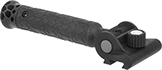
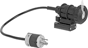
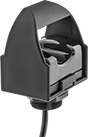
Easy-Hold Abrasive Blaster Safety Switches
 |
Shown in Use |
Reduce fatigue during long blasting sessions—these switches are built into a holder for your blaster hose. The holder has a brace that adjusts to shift most of the hose’s thrust away from your arms and grip, and repositions for comfort or different blasting angles. Switch easily between right- and left-hand use without having to take it apart. The housing has upper and lower rail mounts for optional accessories such as a side handle or flashlight (both sold separately). The mounts swivel around the clamp to keep accessories steady as the hose twists during blasting.
Also known as deadman switches, these switches stop blasting if you lose control. They automatically spring back to the off position to prevent injuries and reduce wasted material. To avoid accidental activation, a secondary safety lock requires an additional motion to begin blasting.
Electric
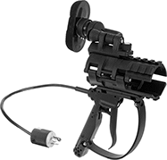 |
Trigger Actuator |
These switches send an electric signal to the control panel on the blaster to stop the spray. Because the signal is electric, these switches respond quickly even when your hose is long. They're recommended for hose that's over 100-ft. long and required by OSHA standards for hose that's over 200-ft. long.
Actuator Style | For Hose OD | Switch Starting Position | No. of Terminals | Switch Designation | Switching Current @ Voltage | Max. Voltage, V DC | Housing Material | Electrical Connection Type | NEMA Type | Wd. | Lg. | Ht. | Features | Each | ||
|---|---|---|---|---|---|---|---|---|---|---|---|---|---|---|---|---|
| Trigger | 1 3/16", 1 1/2", 1 7/8", 2 5/32" | 1 Off | 4 | SPST | 7 amp @ 12V DC 3 amp @ 24V DC | 24 | Plastic | Plug In | L5-15 | 5 1/4" | 11 3/4" | 13" | Adjustable Brace, Secondary Safety Lock, Upper and Lower Rail Mount | 8816N11 | 0000000 |