


Filter by
Switch Action
Number of Buttons
Switch Starting Position
Switch Designation
Switch Type
Voltage
Body Material
Push-Button Shape

Push-Button Style

Number of Terminals
Illumination
Wetted Parts Material
Actuator Style

For Use With
Actuator Color
Export Control Classification Number (ECCN)
REACH
U.S.–Mexico–Canada Agreement (USMCA) Qualifying
DFARS Specialty Metals
Calibrated With

About Electrical Switches
Choose a switch with the right trigger type, number of inputs, and control functions to power your equipment.
Handle Push-Button Switches
Style A
Status Indicators—Switches with status indicators alert you when a switch has been actuated.
Handles without Switch—Add a matching handle without a switch to keep door pulls uniform.
Push-Button Switches | Handles without Switch | ||||||||||||||
|---|---|---|---|---|---|---|---|---|---|---|---|---|---|---|---|
No. of Circuits Controlled | Switch Starting Position | Switch Action | Actuator Color (Switch Designation) | No. of Terminals | Switching Current @ Voltage | Max. Voltage | Handle Lg. | No. of Poles | Electrical Connection | Each | Each | ||||
Glass-Filled Nylon Handle—Status Indicators | |||||||||||||||
| 2 | 1 Off and 1 On | Momentary | Blue (DPST-1NO/1NC) | 4 | 1 amp @ 115V AC, 4 amp @ 28V DC | 115V AC 28V DC | 6 5/16" | 8 | M12 | 7095N11 | 0000000 | 7095N12 | 000000 | ||
Flow Switches with Sight
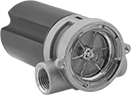 |
Flow Set Point, gpm | Max. Pressure @ Temp. | Temp. Range, ° F | Max. Switching Current @ Voltage | Mounting Position | End-to-End Lg. | Certification | Each | |||
|---|---|---|---|---|---|---|---|---|---|---|
Polypropylene Body with Polypropylene Fittings | ||||||||||
1/4 NPT Female | ||||||||||
| 0.1 to 5 | 100 psi @ 70° F | 33 to 180 | 95 mA @ 115V AC | Any Angle | 3 1/16" | CE Marked UL Recognized Component | 4138K11 | 0000000 | ||
1/2 NPT Female | ||||||||||
| 1.5 to 20 | 100 psi @ 70° F | 33 to 180 | 95 mA @ 115V AC | Any Angle | 3 1/16" | CE Marked UL Recognized Component | 4138K12 | 000000 | ||
Brass Body with Brass Fittings | ||||||||||
1/4 NPT Female | ||||||||||
| 0.1 to 5 | 200 psi @ 70° F | 33 to 212 | 95 mA @ 115V AC | Any Angle | 3" | CE Marked UL Recognized Component | 4138K13 | 000000 | ||
1/2 NPT Female | ||||||||||
| 1.5 to 20 | 200 psi @ 70° F | 33 to 212 | 95 mA @ 115V AC | Any Angle | 3" | CE Marked UL Recognized Component | 4138K14 | 000000 | ||
3/4 NPT Female | ||||||||||
| 5 to 30 | 200 psi @ 70° F | 33 to 212 | 95 mA @ 115V AC | Any Angle | 3 15/16" | CE Marked UL Recognized Component | 4138K15 | 000000 | ||
1 NPT Female | ||||||||||
| 8 to 60 | 200 psi @ 70° F | 33 to 212 | 95 mA @ 115V AC | Any Angle | 3 15/16" | CE Marked UL Recognized Component | 4138K16 | 000000 | ||
316 Stainless Steel Body with 316 Stainless Steel Fittings | ||||||||||
1/2 NPT Female | ||||||||||
| 1.5 to 20 | 200 psi @ 70° F | 33 to 212 | 95 mA @ 115V AC | Any Angle | 3" | CE Marked UL Recognized Component | 4138K18 | 000000 | ||
3/4 NPT Female | ||||||||||
| 5 to 30 | 200 psi @ 70° F | 33 to 212 | 95 mA @ 115V AC | Any Angle | 3 15/16" | CE Marked UL Recognized Component | 4138K19 | 000000 | ||
1 NPT Female | ||||||||||
| 8 to 60 | 200 psi @ 70° F | 33 to 212 | 95 mA @ 115V AC | Any Angle | 3 15/16" | CE Marked UL Recognized Component | 4138K21 | 000000 | ||
