


Measure your pipe and fittings to identify their pipe size, thread size, schedule, and thread type. Then, find compatible components.


Low-Pressure Iron and Steel Threaded Pipe Fittings
Pipe Size | Pressure Class | Material | Max. Pressure @ Temp. | Max. Steam Pressure @ Temp. | Certification | Each | |||
|---|---|---|---|---|---|---|---|---|---|
NPT Female | |||||||||
 Female | |||||||||
| 1/8 | 150 | Iron | 150 psi @ 72° F | 150 psi @ 350° F | UL Listed | 44605K151 | 00000 | ||
| 1/4 | 150 | Iron | 150 psi @ 72° F | 150 psi @ 350° F | UL Listed | 44605K152 | 0000 | ||
| 3/8 | 150 | Iron | 150 psi @ 72° F | 150 psi @ 350° F | UL Listed | 44605K153 | 0000 | ||
| 1/2 | 150 | Iron | 150 psi @ 72° F | 150 psi @ 350° F | UL Listed | 44605K154 | 0000 | ||
| 3/4 | 150 | Iron | 150 psi @ 72° F | 150 psi @ 350° F | UL Listed | 44605K155 | 0000 | ||
| 1 | 150 | Iron | 150 psi @ 72° F | 150 psi @ 350° F | UL Listed | 44605K156 | 00000 | ||
| 1 1/4 | 150 | Iron | 150 psi @ 72° F | 150 psi @ 350° F | UL Listed | 44605K157 | 00000 | ||
| 1 1/2 | 150 | Iron | 150 psi @ 72° F | 150 psi @ 350° F | UL Listed | 44605K158 | 00000 | ||
| 2 | 150 | Iron | 150 psi @ 72° F | 150 psi @ 350° F | UL Listed | 44605K159 | 00000 | ||
| 2 1/2 | 150 | Iron | 150 psi @ 72° F | 150 psi @ 350° F | UL Listed | 44605K51 | 00000 | ||
| 3 | 150 | Iron | 150 psi @ 72° F | 150 psi @ 350° F | UL Listed | 44605K52 | 000000 | ||
| 4 | 150 | Iron | 150 psi @ 72° F | 150 psi @ 350° F | UL Listed | 44605K53 | 000000 | ||
| 6 | 150 | Iron | 150 psi @ 72° F | 150 psi @ 350° F | UL Listed | 44605K533 | 00000000 | ||
BSPT Female | |||||||||
Female | |||||||||
| 1/4 | 150 | Iron | 150 psi @ 72° F | 150 psi @ 360° F | — | 4778K122 | 0000 | ||
| 3/8 | 150 | Iron | 150 psi @ 72° F | 150 psi @ 360° F | — | 4778K123 | 0000 | ||
| 1/2 | 150 | Iron | 150 psi @ 72° F | 150 psi @ 360° F | — | 4778K124 | 0000 | ||
| 3/4 | 150 | Iron | 150 psi @ 72° F | 150 psi @ 360° F | — | 4778K125 | 0000 | ||
| 1 | 150 | Iron | 150 psi @ 72° F | 150 psi @ 360° F | — | 4778K126 | 00000 | ||
| 1 1/4 | 150 | Iron | 150 psi @ 72° F | 150 psi @ 360° F | — | 4778K127 | 00000 | ||
| 1 1/2 | 150 | Iron | 150 psi @ 72° F | 150 psi @ 360° F | — | 4778K128 | 00000 | ||
| 2 | 150 | Iron | 150 psi @ 72° F | 150 psi @ 360° F | — | 4778K129 | 00000 | ||
| 2 1/2 | 150 | Iron | 150 psi @ 72° F | 150 psi @ 360° F | — | 4778K13 | 00000 | ||
 |
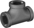
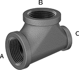
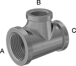
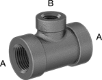
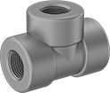
Female × Female × Male |
Pipe Size | |||||||||||
|---|---|---|---|---|---|---|---|---|---|---|---|
(A) | (B) | (C) | Pressure Class | Material | Max. Pressure @ Temp. | Max. Steam Pressure @ Temp. | Certification | Each | |||
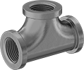
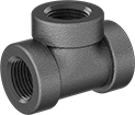
NPT Female × NPT Female × NPT Male | |||||||||||
| 1/4 | 1/4 | 1/4 | 150 | Iron | 150 psi @ 72° F | 150 psi @ 350° F | UL Listed | 44605K401 | 000000 | ||
| 3/8 | 3/8 | 3/8 | 150 | Iron | 150 psi @ 72° F | 150 psi @ 350° F | UL Listed | 44605K402 | 00000 | ||
| 1/2 | 1/2 | 1/2 | 150 | Iron | 150 psi @ 72° F | 150 psi @ 350° F | UL Listed | 44605K403 | 00000 | ||
| 3/4 | 3/4 | 3/4 | 150 | Iron | 150 psi @ 72° F | 150 psi @ 350° F | UL Listed | 44605K404 | 00000 | ||
| 1 | 1 | 1 | 150 | Iron | 150 psi @ 72° F | 150 psi @ 350° F | UL Listed | 44605K405 | 00000 | ||
| 1 1/4 | 1 1/4 | 1 1/4 | 150 | Iron | 150 psi @ 72° F | 150 psi @ 350° F | UL Listed | 44605K406 | 00000 | ||
| 1 1/2 | 1 1/2 | 1 1/2 | 150 | Iron | 150 psi @ 72° F | 150 psi @ 350° F | UL Listed | 44605K407 | 00000 | ||
| 2 | 2 | 2 | 150 | Iron | 150 psi @ 72° F | 150 psi @ 350° F | UL Listed | 44605K408 | 000000 | ||
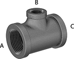 |  |
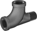
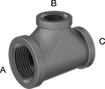
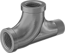
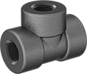
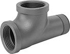
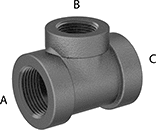
Female x Female x Female | Female × Male × Female |
Pipe Size | |||||||||||
|---|---|---|---|---|---|---|---|---|---|---|---|
(A) | (B) | (C) | Pressure Class | Material | Max. Pressure @ Temp. | Max. Steam Pressure @ Temp. | Certification | Each | |||
NPT Female × NPT Male × NPT Female | |||||||||||
| 2 | 3 | 2 | 150 | Iron | 300 psi @ 72° F | 150 psi @ 350° F | UL Listed | 44605K477 | 000000 | ||
NPT Female × NPT Female × NPT Female | |||||||||||
| 1/8 | 1/4 | 1/8 | 150 | Iron | 150 psi @ 72° F | 150 psi @ 350° F | UL Listed | 44605K781 | 00000 | ||
| 1/4 | 1/8 | 1/4 | 150 | Iron | 150 psi @ 72° F | 150 psi @ 350° F | UL Listed | 44605K782 | 00000 | ||
| 3/8 | 1/4 | 3/8 | 150 | Iron | 150 psi @ 72° F | 150 psi @ 350° F | UL Listed | 44605K783 | 00000 | ||
| 3/8 | 1/2 | 3/8 | 150 | Iron | 150 psi @ 72° F | 150 psi @ 350° F | UL Listed | 44605K511 | 00000 | ||
| 1/2 | 1/4 | 1/2 | 150 | Iron | 150 psi @ 72° F | 150 psi @ 350° F | UL Listed | 44605K372 | 0000 | ||
| 1/2 | 3/8 | 1/2 | 150 | Iron | 150 psi @ 72° F | 150 psi @ 350° F | UL Listed | 44605K371 | 00000 | ||
| 1/2 | 3/4 | 1/2 | 150 | Iron | 150 psi @ 72° F | 150 psi @ 350° F | UL Listed | 44605K451 | 00000 | ||
| 1/2 | 1 | 1/2 | 150 | Iron | 150 psi @ 72° F | 150 psi @ 350° F | — | 44605K628 | 00000 | ||
| 3/4 | 1/4 | 3/4 | 150 | Iron | 150 psi @ 72° F | 150 psi @ 350° F | UL Listed | 44605K375 | 00000 | ||
| 3/4 | 3/8 | 3/4 | 150 | Iron | 150 psi @ 72° F | 150 psi @ 350° F | UL Listed | 44605K468 | 00000 | ||
| 3/4 | 1/2 | 3/4 | 150 | Iron | 150 psi @ 72° F | 150 psi @ 350° F | UL Listed | 44605K374 | 00000 | ||
| 3/4 | 1 | 3/4 | 150 | Iron | 150 psi @ 72° F | 150 psi @ 350° F | UL Listed | 44605K455 | 00000 | ||
| 3/4 | 1 1/4 | 3/4 | 150 | Iron | 150 psi @ 72° F | 150 psi @ 350° F | UL Listed | 44605K785 | 00000 | ||
| 1 | 1/4 | 1 | 150 | Iron | 150 psi @ 72° F | 150 psi @ 350° F | — | 44605K627 | 00000 | ||
| 1 | 3/8 | 1 | 150 | Iron | 150 psi @ 72° F | 150 psi @ 350° F | UL Listed | 44605K453 | 00000 | ||
| 1 | 1/2 | 1 | 150 | Iron | 150 psi @ 72° F | 150 psi @ 350° F | UL Listed | 44605K452 | 00000 | ||
| 1 | 3/4 | 1 | 150 | Iron | 150 psi @ 72° F | 150 psi @ 350° F | UL Listed | 44605K376 | 00000 | ||
| 1 | 1 1/4 | 1 | 150 | Iron | 150 psi @ 72° F | 150 psi @ 350° F | UL Listed | 44605K635 | 00000 | ||
| 1 | 1 1/2 | 1 | 150 | Iron | 150 psi @ 72° F | 150 psi @ 350° F | UL Listed | 44605K788 | 00000 | ||
| 1 | 2 | 1 | 150 | Iron | 150 psi @ 72° F | 150 psi @ 350° F | UL Listed | 44605K792 | 00000 | ||
| 1 1/4 | 3/8 | 1 1/4 | 150 | Iron | 150 psi @ 72° F | 150 psi @ 350° F | UL Listed | 44605K784 | 00000 | ||
| 1 1/4 | 1/2 | 1 1/4 | 150 | Iron | 150 psi @ 72° F | 150 psi @ 350° F | UL Listed | 44605K458 | 00000 | ||
| 1 1/4 | 3/4 | 1 1/4 | 150 | Iron | 150 psi @ 72° F | 150 psi @ 350° F | UL Listed | 44605K457 | 00000 | ||
| 1 1/4 | 1 | 1 1/4 | 150 | Iron | 150 psi @ 72° F | 150 psi @ 350° F | UL Listed | 44605K456 | 00000 | ||
| 1 1/4 | 1 1/2 | 1 1/4 | 150 | Iron | 150 psi @ 72° F | 150 psi @ 350° F | UL Listed | 44605K787 | 00000 | ||
| 1 1/4 | 2 | 1 1/4 | 150 | Iron | 150 psi @ 72° F | 150 psi @ 350° F | UL Listed | 44605K791 | 00000 | ||
| 1 1/2 | 1/2 | 1 1/2 | 150 | Iron | 150 psi @ 72° F | 150 psi @ 350° F | UL Listed | 44605K462 | 00000 | ||
| 1 1/2 | 3/4 | 1 1/2 | 150 | Iron | 150 psi @ 72° F | 150 psi @ 350° F | UL Listed | 44605K461 | 00000 | ||
| 1 1/2 | 1 | 1 1/2 | 150 | Iron | 150 psi @ 72° F | 150 psi @ 350° F | UL Listed | 44605K382 | 00000 | ||
| 1 1/2 | 1 1/4 | 1 1/2 | 150 | Iron | 150 psi @ 72° F | 150 psi @ 350° F | UL Listed | 44605K459 | 00000 | ||
| 1 1/2 | 2 | 1 1/2 | 150 | Iron | 150 psi @ 72° F | 150 psi @ 350° F | UL Listed | 44605K789 | 00000 | ||
| 2 | 1/2 | 2 | 150 | Iron | 150 psi @ 72° F | 150 psi @ 350° F | UL Listed | 44605K465 | 00000 | ||
| 2 | 3/4 | 2 | 150 | Iron | 150 psi @ 72° F | 150 psi @ 350° F | UL Listed | 44605K464 | 00000 | ||
| 2 | 1 | 2 | 150 | Iron | 150 psi @ 72° F | 150 psi @ 350° F | UL Listed | 44605K463 | 00000 | ||
| 2 | 1 1/4 | 2 | 150 | Iron | 150 psi @ 72° F | 150 psi @ 350° F | UL Listed | 44605K639 | 00000 | ||
| 2 | 1 1/2 | 2 | 150 | Iron | 150 psi @ 72° F | 150 psi @ 350° F | UL Listed | 44605K383 | 00000 | ||
| 2 | 2 1/2 | 2 | 150 | Iron | 150 psi @ 72° F | 150 psi @ 350° F | UL Listed | 44605K793 | 000000 | ||
| 2 1/2 | 3/4 | 2 1/2 | 150 | Iron | 150 psi @ 72° F | 150 psi @ 350° F | — | 44605K649 | 000000 | ||
| 2 1/2 | 1 | 2 1/2 | 150 | Iron | 150 psi @ 72° F | 150 psi @ 350° F | — | 44605K648 | 000000 | ||
| 2 1/2 | 1 1/4 | 2 1/2 | 150 | Iron | 150 psi @ 72° F | 150 psi @ 350° F | — | 44605K647 | 000000 | ||
| 2 1/2 | 1 1/2 | 2 1/2 | 150 | Iron | 150 psi @ 72° F | 150 psi @ 350° F | — | 44605K646 | 000000 | ||
| 2 1/2 | 2 | 2 1/2 | 150 | Iron | 150 psi @ 72° F | 150 psi @ 350° F | — | 44605K645 | 000000 | ||
| 2 1/2 | 3 | 2 1/2 | 150 | Iron | 150 psi @ 72° F | 150 psi @ 350° F | UL Listed | 44605K794 | 000000 | ||
| 3 | 3/4 | 3 | 150 | Iron | 150 psi @ 72° F | 150 psi @ 350° F | — | 44605K653 | 000000 | ||
| 3 | 1 | 3 | 150 | Iron | 150 psi @ 72° F | 150 psi @ 350° F | UL Listed | 44605K524 | 000000 | ||
| 3 | 1 1/4 | 3 | 150 | Iron | 150 psi @ 72° F | 150 psi @ 350° F | UL Listed | 44605K652 | 000000 | ||
| 3 | 1 1/2 | 3 | 150 | Iron | 150 psi @ 72° F | 150 psi @ 350° F | UL Listed | 44605K651 | 000000 | ||
| 3 | 2 | 3 | 150 | Iron | 150 psi @ 72° F | 150 psi @ 350° F | UL Listed | 44605K525 | 000000 | ||
| 3 | 2 1/2 | 3 | 150 | Iron | 150 psi @ 72° F | 150 psi @ 350° F | UL Listed | 44605K526 | 000000 | ||
| 4 | 3 | 4 | 150 | Iron | 150 psi @ 72° F | 150 psi @ 350° F | — | 44605K683 | 000000 | ||
 |
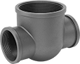
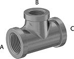
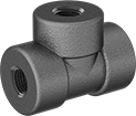
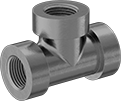
Female x Female x Female |
Pipe Size | |||||||||||
|---|---|---|---|---|---|---|---|---|---|---|---|
(A) | (B) | (C) | Pressure Class | Material | Max. Pressure @ Temp. | Max. Steam Pressure @ Temp. | Certification | Each | |||
NPT Female × NPT Female × NPT Female | |||||||||||
| 3/8 | 3/8 | 1/2 | 150 | Iron | 150 psi @ 72° F | 150 psi @ 350° F | UL Listed | 44605K513 | 000000 | ||
| 1/2 | 1/2 | 1/4 | 150 | Iron | 150 psi @ 72° F | 150 psi @ 350° F | — | 44605K512 | 0000 | ||
| 1/2 | 1/2 | 3/8 | 150 | Iron | 150 psi @ 72° F | 150 psi @ 350° F | UL Listed | 44605K373 | 00000 | ||
| 1/2 | 1/2 | 3/4 | 150 | Iron | 150 psi @ 72° F | 150 psi @ 350° F | UL Listed | 44605K449 | 00000 | ||
| 1/2 | 1/2 | 1 | 150 | Iron | 150 psi @ 72° F | 150 psi @ 350° F | UL Listed | 44605K381 | 00000 | ||
| 3/4 | 3/4 | 1/4 | 150 | Iron | 150 psi @ 72° F | 150 psi @ 350° F | UL Listed | 44605K773 | 00000 | ||
| 3/4 | 3/4 | 3/8 | 150 | Iron | 150 psi @ 72° F | 150 psi @ 350° F | UL Listed | 44605K772 | 00000 | ||
| 3/4 | 3/4 | 1/2 | 150 | Iron | 150 psi @ 72° F | 150 psi @ 350° F | UL Listed | 44605K448 | 00000 | ||
| 3/4 | 3/4 | 1 | 150 | Iron | 150 psi @ 72° F | 150 psi @ 350° F | UL Listed | 44605K378 | 00000 | ||
| 3/4 | 3/4 | 1 1/4 | 150 | Iron | 150 psi @ 72° F | 150 psi @ 350° F | UL Listed | 44605K633 | 00000 | ||
| 3/4 | 3/4 | 1 1/2 | 150 | Iron | 150 psi @ 72° F | 150 psi @ 350° F | — | 44605K517 | 00000 | ||
| 1 | 1 | 1/4 | 150 | Iron | 150 psi @ 72° F | 150 psi @ 350° F | UL Listed | 44605K516 | 00000 | ||
| 1 | 1 | 1/2 | 150 | Iron | 150 psi @ 72° F | 150 psi @ 350° F | UL Listed | 44605K379 | 00000 | ||
| 1 | 1 | 3/4 | 150 | Iron | 150 psi @ 72° F | 150 psi @ 350° F | UL Listed | 44605K377 | 00000 | ||
| 1 | 1 | 1 1/4 | 150 | Iron | 150 psi @ 72° F | 150 psi @ 350° F | UL Listed | 44605K629 | 00000 | ||
| 1 | 1 | 1 1/2 | 150 | Iron | 150 psi @ 72° F | 150 psi @ 350° F | UL Listed | 44605K518 | 00000 | ||
| 1 1/4 | 1 1/4 | 1/2 | 150 | Iron | 150 psi @ 72° F | 150 psi @ 350° F | UL Listed | 44605K634 | 00000 | ||
| 1 1/4 | 1 1/4 | 3/4 | 150 | Iron | 150 psi @ 72° F | 150 psi @ 350° F | UL Listed | 44605K632 | 00000 | ||
| 1 1/4 | 1 1/4 | 1 1/2 | 150 | Iron | 150 psi @ 72° F | 150 psi @ 350° F | UL Listed | 44605K637 | 00000 | ||
| 1 1/2 | 1 1/2 | 1/2 | 150 | Iron | 150 psi @ 72° F | 150 psi @ 350° F | UL Listed | 44605K774 | 00000 | ||
| 1 1/2 | 1 1/2 | 3/4 | 150 | Iron | 150 psi @ 72° F | 150 psi @ 350° F | UL Listed | 44605K519 | 00000 | ||
| 1 1/2 | 1 1/2 | 1 | 150 | Iron | 150 psi @ 72° F | 150 psi @ 350° F | UL Listed | 44605K521 | 00000 | ||
| 1 1/2 | 1 1/2 | 1 1/4 | 150 | Iron | 150 psi @ 72° F | 150 psi @ 350° F | UL Listed | 44605K636 | 00000 | ||
| 1 1/2 | 1 1/2 | 2 | 150 | Iron | 150 psi @ 72° F | 150 psi @ 350° F | UL Listed | 44605K641 | 00000 | ||
| 2 | 2 | 1/2 | 150 | Iron | 150 psi @ 72° F | 150 psi @ 350° F | UL Listed | 44605K776 | 00000 | ||
| 2 | 2 | 3/4 | 150 | Iron | 150 psi @ 72° F | 150 psi @ 350° F | UL Listed | 44605K775 | 00000 | ||
| 2 | 2 | 1 | 150 | Iron | 150 psi @ 72° F | 150 psi @ 350° F | UL Listed | 44605K522 | 00000 | ||
| 2 | 2 | 1 1/4 | 150 | Iron | 150 psi @ 72° F | 150 psi @ 350° F | UL Listed | 44605K643 | 00000 | ||
| 2 | 2 | 1 1/2 | 150 | Iron | 150 psi @ 72° F | 150 psi @ 350° F | UL Listed | 44605K466 | 00000 | ||
| 2 | 2 | 3 | 150 | Iron | 150 psi @ 72° F | 150 psi @ 350° F | UL Listed | 44605K527 | 000000 | ||
| 2 1/2 | 2 1/2 | 1 1/2 | 150 | Iron | 150 psi @ 72° F | 150 psi @ 350° F | UL Listed | 44605K778 | 000000 | ||
| 2 1/2 | 2 1/2 | 2 | 150 | Iron | 150 psi @ 72° F | 150 psi @ 350° F | UL Listed | 44605K777 | 000000 | ||
| 3 | 3 | 2 | 150 | Iron | 150 psi @ 72° F | 150 psi @ 350° F | UL Listed | 44605K779 | 000000 | ||
 |
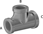
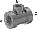
Female × Female × Female |
Pipe Size | |||||||||||
|---|---|---|---|---|---|---|---|---|---|---|---|
(A) | (B) | (C) | Pressure Class | Material | Max. Pressure @ Temp. | Max. Steam Pressure @ Temp. | Certification | Each | |||
NPT Female × NPT Female × NPT Female | |||||||||||
| 1 | 1/2 | 3/4 | 150 | Iron | 150 psi @ 72° F | 150 psi @ 350° F | UL Listed | 44605K454 | 000000 | ||
| 1 1/4 | 1/2 | 1 | 150 | Iron | 150 psi @ 72° F | 150 psi @ 350° F | UL Listed | 44605K795 | 00000 | ||
| 1 1/4 | 3/4 | 1 | 150 | Iron | 150 psi @ 72° F | 150 psi @ 350° F | UL Listed | 44605K631 | 00000 | ||
| 1 1/4 | 1 | 1/2 | 150 | Iron | 150 psi @ 72° F | 150 psi @ 350° F | UL Listed | 44605K796 | 00000 | ||
| 1 1/2 | 1/2 | 1 1/4 | 150 | Iron | 150 psi @ 72° F | 150 psi @ 350° F | UL Listed | 44605K798 | 00000 | ||
| 1 1/2 | 3/4 | 1 1/4 | 150 | Iron | 150 psi @ 72° F | 150 psi @ 350° F | UL Listed | 44605K638 | 00000 | ||
| 1 1/2 | 1 | 1 1/4 | 150 | Iron | 150 psi @ 72° F | 150 psi @ 350° F | UL Listed | 44605K797 | 00000 | ||
| 1 1/2 | 1 1/4 | 1 | 150 | Iron | 150 psi @ 72° F | 150 psi @ 350° F | UL Listed | 44605K799 | 00000 | ||
| 2 | 1 | 1 1/2 | 150 | Iron | 150 psi @ 72° F | 150 psi @ 350° F | UL Listed | 44605K467 | 00000 | ||
| 2 | 1 1/4 | 1 1/2 | 150 | Iron | 150 psi @ 72° F | 150 psi @ 350° F | UL Listed | 44605K801 | 00000 | ||
| 2 | 1 1/2 | 1 1/4 | 150 | Iron | 150 psi @ 72° F | 150 psi @ 350° F | UL Listed | 44605K802 | 00000 | ||
| 2 1/2 | 2 | 1 1/2 | 150 | Iron | 150 psi @ 72° F | 150 psi @ 350° F | UL Listed | 44605K803 | 000000 | ||
| 3 | 2 | 2 1/2 | 150 | Iron | 150 psi @ 72° F | 150 psi @ 350° F | UL Listed | 44605K804 | 000000 | ||
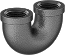 |
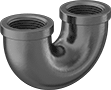
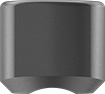
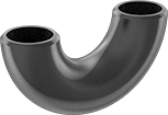
Pipe Size | Material | Max. Pressure @ Temp. | Max. Steam Pressure @ Temp. | Certification | Shape | Each | |||
|---|---|---|---|---|---|---|---|---|---|
NPT Female | |||||||||
| 1/2 | Iron | 150 psi @ 72° F | 150 psi @ 350° F | UL Listed | 180° Bend | 44605K563 | 000000 | ||
| 3/4 | Iron | 150 psi @ 72° F | 150 psi @ 350° F | UL Listed | 180° Bend | 44605K564 | 00000 | ||
| 1 | Iron | 150 psi @ 72° F | 150 psi @ 350° F | — | 180° Bend | 44605K565 | 00000 | ||
| 1 1/4 | Iron | 150 psi @ 72° F | 150 psi @ 350° F | UL Listed | 180° Bend | 44605K566 | 00000 | ||
| 1 1/2 | Iron | 150 psi @ 72° F | 150 psi @ 350° F | UL Listed | 180° Bend | 44605K567 | 000000 | ||
| 2 | Iron | 150 psi @ 72° F | 150 psi @ 350° F | UL Listed | 180° Bend | 44605K568 | 000000 | ||
 |
Pipe Size | Finished Material | Max. Pressure @ Temp. | Max. Steam Pressure @ Temp. | Each | |||
|---|---|---|---|---|---|---|---|
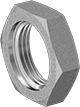
NPSL Female | |||||||
| 1/4 | Steel | Not Rated | Not Rated | 44605K434 | 00000 | ||
| 3/8 | Iron | Not Rated | Not Rated | 44605K211 | 0000 | ||
| 1/2 | Iron | Not Rated | Not Rated | 44605K212 | 0000 | ||
| 3/4 | Iron | Not Rated | Not Rated | 44605K213 | 0000 | ||
| 1 | Iron | Not Rated | Not Rated | 44605K214 | 00000 | ||
| 1 1/4 | Iron | Not Rated | Not Rated | 44605K215 | 0000 | ||
| 1 1/2 | Iron | Not Rated | Not Rated | 44605K216 | 00000 | ||
| 2 | Iron | Not Rated | Not Rated | 44605K217 | 00000 | ||
Low-Pressure Galvanized Iron and Steel Threaded Pipe Fittings
Pipe Size | Pressure Class | Material | Max. Pressure @ Temp. | Max. Steam Pressure @ Temp. | Certification | Each | |||
|---|---|---|---|---|---|---|---|---|---|
NPT Female | |||||||||
 | |||||||||
| 1/8 | 150 | Galvanized Iron | 150 psi @ 72° F | 150 psi @ 350° F | UL Listed | 4638K129 | 00000 | ||
| 1/4 | 150 | Galvanized Iron | 150 psi @ 72° F | 150 psi @ 350° F | UL Listed | 4638K121 | 0000 | ||
| 3/8 | 150 | Galvanized Iron | 150 psi @ 72° F | 150 psi @ 350° F | UL Listed | 4638K122 | 0000 | ||
| 1/2 | 150 | Galvanized Iron | 150 psi @ 72° F | 150 psi @ 350° F | UL Listed | 4638K123 | 0000 | ||
| 3/4 | 150 | Galvanized Iron | 150 psi @ 72° F | 150 psi @ 350° F | UL Listed | 4638K124 | 0000 | ||
| 1 | 150 | Galvanized Iron | 150 psi @ 72° F | 150 psi @ 350° F | UL Listed | 4638K125 | 00000 | ||
| 1 1/4 | 150 | Galvanized Iron | 150 psi @ 72° F | 150 psi @ 350° F | UL Listed | 4638K126 | 00000 | ||
| 1 1/2 | 150 | Galvanized Iron | 150 psi @ 72° F | 150 psi @ 350° F | UL Listed | 4638K127 | 00000 | ||
| 2 | 150 | Galvanized Iron | 150 psi @ 72° F | 150 psi @ 350° F | UL Listed | 4638K128 | 00000 | ||
| 2 1/2 | 150 | Galvanized Iron | 150 psi @ 72° F | 150 psi @ 350° F | UL Listed | 4638K154 | 000000 | ||
| 3 | 150 | Galvanized Iron | 150 psi @ 72° F | 150 psi @ 350° F | UL Listed | 4638K155 | 000000 | ||
| 4 | 150 | Galvanized Iron | 150 psi @ 72° F | 150 psi @ 350° F | UL Listed | 4638K156 | 000000 | ||
| 6 | 150 | Galvanized Iron | 150 psi @ 72° F | 150 psi @ 350° F | UL Listed | 4638K398 | 00000000 | ||
BSPT Female | |||||||||
| |||||||||
| 1/4 | 150 | Galvanized Iron | 150 psi @ 72° F | 150 psi @ 360° F | — | 4888K122 | 0000 | ||
| 3/8 | 150 | Galvanized Iron | 150 psi @ 72° F | 150 psi @ 360° F | — | 4888K123 | 0000 | ||
| 1/2 | 150 | Galvanized Iron | 150 psi @ 72° F | 150 psi @ 360° F | — | 4888K124 | 0000 | ||
| 3/4 | 150 | Galvanized Iron | 150 psi @ 72° F | 150 psi @ 360° F | — | 4888K125 | 0000 | ||
| 1 | 150 | Galvanized Iron | 150 psi @ 72° F | 150 psi @ 360° F | — | 4888K126 | 00000 | ||
| 1 1/2 | 150 | Galvanized Iron | 150 psi @ 72° F | 150 psi @ 360° F | — | 4888K128 | 00000 | ||
| 2 | 150 | Galvanized Iron | 150 psi @ 72° F | 150 psi @ 360° F | — | 4888K129 | 00000 | ||
 |
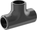
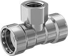
Female x Female x Male |
Pipe Size | |||||||||||
|---|---|---|---|---|---|---|---|---|---|---|---|
(A) | (B) | (C) | Pressure Class | Material | Max. Pressure @ Temp. | Max. Steam Pressure @ Temp. | Certification | Each | |||
NPT Female × NPT Female × NPT Male | |||||||||||
| 1/4 | 1/4 | 1/4 | 150 | Galvanized Iron | 150 psi @ 72° F | 150 psi @ 350° F | UL Listed | 4638K366 | 000000 | ||
| 3/8 | 3/8 | 3/8 | 150 | Galvanized Iron | 150 psi @ 72° F | 150 psi @ 350° F | UL Listed | 4638K367 | 00000 | ||
| 1/2 | 1/2 | 1/2 | 150 | Galvanized Iron | 150 psi @ 72° F | 150 psi @ 350° F | UL Listed | 4638K368 | 00000 | ||
| 3/4 | 3/4 | 3/4 | 150 | Galvanized Iron | 150 psi @ 72° F | 150 psi @ 350° F | UL Listed | 4638K369 | 00000 | ||
| 1 | 1 | 1 | 150 | Galvanized Iron | 150 psi @ 72° F | 150 psi @ 350° F | UL Listed | 4638K371 | 00000 | ||
| 1 1/4 | 1 1/4 | 1 1/4 | 150 | Galvanized Iron | 150 psi @ 72° F | 150 psi @ 350° F | UL Listed | 4638K372 | 00000 | ||
| 1 1/2 | 1 1/2 | 1 1/2 | 150 | Galvanized Iron | 150 psi @ 72° F | 150 psi @ 350° F | UL Listed | 4638K373 | 00000 | ||
| 2 | 2 | 2 | 150 | Galvanized Iron | 150 psi @ 72° F | 150 psi @ 350° F | UL Listed | 4638K374 | 000000 | ||
 |
Female x Female x Female |
Pipe Size | |||||||||||
|---|---|---|---|---|---|---|---|---|---|---|---|
(A) | (B) | (C) | Pressure Class | Material | Max. Pressure @ Temp. | Max. Steam Pressure @ Temp. | Certification | Each | |||
NPT Female × NPT Female × NPT Female | |||||||||||
| 1/8 | 1/4 | 1/8 | 150 | Galvanized Iron | 150 psi @ 72° F | 150 psi @ 350° F | UL Listed | 4638K415 | 000000 | ||
| 1/4 | 1/8 | 1/4 | 150 | Galvanized Iron | 150 psi @ 72° F | 150 psi @ 350° F | UL Listed | 4638K414 | 00000 | ||
| 1/4 | 3/8 | 1/4 | 150 | Galvanized Iron | 150 psi @ 72° F | 150 psi @ 350° F | UL Listed | 4638K417 | 00000 | ||
| 3/8 | 1/4 | 3/8 | 150 | Galvanized Iron | 150 psi @ 72° F | 150 psi @ 350° F | UL Listed | 4638K416 | 00000 | ||
| 3/8 | 1/2 | 3/8 | 150 | Galvanized Iron | 150 psi @ 72° F | 150 psi @ 350° F | UL Listed | 4638K521 | 00000 | ||
| 1/2 | 1/4 | 1/2 | 150 | Galvanized Iron | 150 psi @ 72° F | 150 psi @ 350° F | UL Listed | 4638K175 | 00000 | ||
| 1/2 | 3/8 | 1/2 | 150 | Galvanized Iron | 150 psi @ 72° F | 150 psi @ 350° F | UL Listed | 4638K174 | 00000 | ||
| 1/2 | 3/4 | 1/2 | 150 | Galvanized Iron | 150 psi @ 72° F | 150 psi @ 350° F | UL Listed | 4638K187 | 00000 | ||
| 1/2 | 1 | 1/2 | 150 | Galvanized Iron | 150 psi @ 72° F | 150 psi @ 350° F | UL Listed | 4638K752 | 00000 | ||
| 3/4 | 1/4 | 3/4 | 150 | Galvanized Iron | 150 psi @ 72° F | 150 psi @ 350° F | UL Listed | 4638K178 | 00000 | ||
| 3/4 | 3/8 | 3/4 | 150 | Galvanized Iron | 150 psi @ 72° F | 150 psi @ 350° F | UL Listed | 4638K188 | 00000 | ||
| 3/4 | 1/2 | 3/4 | 150 | Galvanized Iron | 150 psi @ 72° F | 150 psi @ 350° F | UL Listed | 4638K265 | 00000 | ||
| 3/4 | 1 | 3/4 | 150 | Galvanized Iron | 150 psi @ 72° F | 150 psi @ 350° F | UL Listed | 4638K177 | 00000 | ||
| 3/4 | 1 1/4 | 3/4 | 150 | Galvanized Iron | 150 psi @ 72° F | 150 psi @ 350° F | UL Listed | 4638K419 | 00000 | ||
| 1 | 1/4 | 1 | 150 | Galvanized Iron | 150 psi @ 72° F | 150 psi @ 350° F | UL Listed | 4638K751 | 00000 | ||
| 1 | 3/8 | 1 | 150 | Galvanized Iron | 150 psi @ 72° F | 150 psi @ 350° F | UL Listed | 4638K212 | 00000 | ||
| 1 | 1/2 | 1 | 150 | Galvanized Iron | 150 psi @ 72° F | 150 psi @ 350° F | UL Listed | 4638K213 | 00000 | ||
| 1 | 3/4 | 1 | 150 | Galvanized Iron | 150 psi @ 72° F | 150 psi @ 350° F | UL Listed | 4638K179 | 00000 | ||
| 1 | 1 1/4 | 1 | 150 | Galvanized Iron | 150 psi @ 72° F | 150 psi @ 350° F | UL Listed | 4638K758 | 00000 | ||
| 1 | 1 1/2 | 1 | 150 | Galvanized Iron | 150 psi @ 72° F | 150 psi @ 350° F | UL Listed | 4638K622 | 00000 | ||
| 1 | 2 | 1 | 150 | Galvanized Iron | 150 psi @ 72° F | 150 psi @ 350° F | UL Listed | 4638K627 | 00000 | ||
| 1 1/4 | 3/8 | 1 1/4 | 150 | Galvanized Iron | 150 psi @ 72° F | 150 psi @ 350° F | UL Listed | 4638K418 | 00000 | ||
| 1 1/4 | 1/2 | 1 1/4 | 150 | Galvanized Iron | 150 psi @ 72° F | 150 psi @ 350° F | UL Listed | 4638K266 | 00000 | ||
| 1 1/4 | 3/4 | 1 1/4 | 150 | Galvanized Iron | 150 psi @ 72° F | 150 psi @ 350° F | UL Listed | 4638K271 | 00000 | ||
| 1 1/4 | 1 | 1 1/4 | 150 | Galvanized Iron | 150 psi @ 72° F | 150 psi @ 350° F | UL Listed | 4638K272 | 00000 | ||
| 1 1/4 | 1 1/2 | 1 1/4 | 150 | Galvanized Iron | 150 psi @ 72° F | 150 psi @ 350° F | UL Listed | 4638K621 | 00000 | ||
| 1 1/4 | 2 | 1 1/4 | 150 | Galvanized Iron | 150 psi @ 72° F | 150 psi @ 350° F | UL Listed | 4638K626 | 00000 | ||
| 1 1/2 | 1/2 | 1 1/2 | 150 | Galvanized Iron | 150 psi @ 72° F | 150 psi @ 350° F | UL Listed | 4638K273 | 00000 | ||
| 1 1/2 | 3/4 | 1 1/2 | 150 | Galvanized Iron | 150 psi @ 72° F | 150 psi @ 350° F | UL Listed | 4638K274 | 00000 | ||
| 1 1/2 | 1 | 1 1/2 | 150 | Galvanized Iron | 150 psi @ 72° F | 150 psi @ 350° F | UL Listed | 4638K185 | 00000 | ||
| 1 1/2 | 1 1/4 | 1 1/2 | 150 | Galvanized Iron | 150 psi @ 72° F | 150 psi @ 350° F | UL Listed | 4638K275 | 00000 | ||
| 1 1/2 | 2 | 1 1/2 | 150 | Galvanized Iron | 150 psi @ 72° F | 150 psi @ 350° F | UL Listed | 4638K625 | 00000 | ||
| 2 | 1/2 | 2 | 150 | Galvanized Iron | 150 psi @ 72° F | 150 psi @ 350° F | UL Listed | 4638K276 | 00000 | ||
| 2 | 3/4 | 2 | 150 | Galvanized Iron | 150 psi @ 72° F | 150 psi @ 350° F | UL Listed | 4638K277 | 00000 | ||
| 2 | 1 | 2 | 150 | Galvanized Iron | 150 psi @ 72° F | 150 psi @ 350° F | UL Listed | 4638K278 | 00000 | ||
| 2 | 1 1/4 | 2 | 150 | Galvanized Iron | 150 psi @ 72° F | 150 psi @ 350° F | UL Listed | 4638K763 | 00000 | ||
| 2 | 1 1/2 | 2 | 150 | Galvanized Iron | 150 psi @ 72° F | 150 psi @ 350° F | UL Listed | 4638K186 | 00000 | ||
| 2 1/2 | 3/4 | 2 1/2 | 150 | Galvanized Iron | 150 psi @ 72° F | 150 psi @ 350° F | UL Listed | 4638K771 | 000000 | ||
| 2 1/2 | 1 | 2 1/2 | 150 | Galvanized Iron | 150 psi @ 72° F | 150 psi @ 350° F | UL Listed | 4638K769 | 000000 | ||
| 2 1/2 | 1 1/2 | 2 1/2 | 150 | Galvanized Iron | 150 psi @ 72° F | 150 psi @ 350° F | UL Listed | 4638K767 | 000000 | ||
| 2 1/2 | 2 | 2 1/2 | 150 | Galvanized Iron | 150 psi @ 72° F | 150 psi @ 350° F | UL Listed | 4638K766 | 000000 | ||
| 3 | 3/4 | 3 | 150 | Galvanized Iron | 150 psi @ 72° F | 150 psi @ 350° F | UL Listed | 4638K774 | 000000 | ||
| 3 | 1 | 3 | 150 | Galvanized Iron | 150 psi @ 72° F | 150 psi @ 350° F | UL Listed | 4638K534 | 000000 | ||
| 3 | 1 1/4 | 3 | 150 | Galvanized Iron | 150 psi @ 72° F | 150 psi @ 350° F | UL Listed | 4638K773 | 000000 | ||
| 3 | 1 1/2 | 3 | 150 | Galvanized Iron | 150 psi @ 72° F | 150 psi @ 350° F | UL Listed | 4638K772 | 000000 | ||
| 3 | 2 | 3 | 150 | Galvanized Iron | 150 psi @ 72° F | 150 psi @ 350° F | UL Listed | 4638K535 | 000000 | ||
| 3 | 2 1/2 | 3 | 150 | Galvanized Iron | 150 psi @ 72° F | 150 psi @ 350° F | UL Listed | 4638K536 | 000000 | ||
| 4 | 3 | 4 | 150 | Galvanized Iron | 150 psi @ 72° F | 150 psi @ 350° F | UL Listed | 4638K775 | 000000 | ||
 |
Female x Female x Female |
Pipe Size | |||||||||||
|---|---|---|---|---|---|---|---|---|---|---|---|
(A) | (B) | (C) | Pressure Class | Material | Max. Pressure @ Temp. | Max. Steam Pressure @ Temp. | Certification | Each | |||
NPT Female × NPT Female × NPT Female | |||||||||||
| 1/4 | 1/4 | 3/8 | 150 | Galvanized Iron | 150 psi @ 72° F | 150 psi @ 350° F | UL Listed | 4638K988 | 000000 | ||
| 3/8 | 3/8 | 1/2 | 150 | Galvanized Iron | 150 psi @ 72° F | 150 psi @ 350° F | UL Listed | 4638K523 | 00000 | ||
| 1/2 | 1/2 | 1/4 | 150 | Galvanized Iron | 150 psi @ 72° F | 150 psi @ 350° F | UL Listed | 4638K522 | 00000 | ||
| 1/2 | 1/2 | 3/8 | 150 | Galvanized Iron | 150 psi @ 72° F | 150 psi @ 350° F | UL Listed | 4638K176 | 00000 | ||
| 1/2 | 1/2 | 3/4 | 150 | Galvanized Iron | 150 psi @ 72° F | 150 psi @ 350° F | UL Listed | 4638K211 | 00000 | ||
| 1/2 | 1/2 | 1 | 150 | Galvanized Iron | 150 psi @ 72° F | 150 psi @ 350° F | UL Listed | 4638K184 | 00000 | ||
| 3/4 | 3/4 | 1/4 | 150 | Galvanized Iron | 150 psi @ 72° F | 150 psi @ 350° F | UL Listed | 4638K991 | 00000 | ||
| 3/4 | 3/4 | 1/2 | 150 | Galvanized Iron | 150 psi @ 72° F | 150 psi @ 350° F | UL Listed | 4638K189 | 00000 | ||
| 3/4 | 3/4 | 1 | 150 | Galvanized Iron | 150 psi @ 72° F | 150 psi @ 350° F | UL Listed | 4638K182 | 00000 | ||
| 3/4 | 3/4 | 1 1/4 | 150 | Galvanized Iron | 150 psi @ 72° F | 150 psi @ 350° F | UL Listed | 4638K756 | 00000 | ||
| 3/4 | 3/4 | 1 1/2 | 150 | Galvanized Iron | 150 psi @ 72° F | 150 psi @ 350° F | UL Listed | 4638K527 | 00000 | ||
| 1 | 1 | 1/4 | 150 | Galvanized Iron | 150 psi @ 72° F | 150 psi @ 350° F | UL Listed | 4638K526 | 00000 | ||
| 1 | 1 | 1/2 | 150 | Galvanized Iron | 150 psi @ 72° F | 150 psi @ 350° F | UL Listed | 4638K183 | 00000 | ||
| 1 | 1 | 3/4 | 150 | Galvanized Iron | 150 psi @ 72° F | 150 psi @ 350° F | UL Listed | 4638K181 | 00000 | ||
| 1 | 1 | 1 1/4 | 150 | Galvanized Iron | 150 psi @ 72° F | 150 psi @ 350° F | UL Listed | 4638K753 | 00000 | ||
| 1 | 1 | 1 1/2 | 150 | Galvanized Iron | 150 psi @ 72° F | 150 psi @ 350° F | UL Listed | 4638K528 | 00000 | ||
| 1 | 1 | 2 | 150 | Galvanized Iron | 150 psi @ 72° F | 150 psi @ 350° F | UL Listed | 4638K713 | 00000 | ||
| 1 1/4 | 1 1/4 | 1/2 | 150 | Galvanized Iron | 150 psi @ 72° F | 150 psi @ 350° F | UL Listed | 4638K757 | 00000 | ||
| 1 1/4 | 1 1/4 | 3/4 | 150 | Galvanized Iron | 150 psi @ 72° F | 150 psi @ 350° F | UL Listed | 4638K755 | 00000 | ||
| 1 1/4 | 1 1/4 | 1 | 150 | Galvanized Iron | 150 psi @ 72° F | 150 psi @ 350° F | UL Listed | 4638K992 | 00000 | ||
| 1 1/4 | 1 1/4 | 1 1/2 | 150 | Galvanized Iron | 150 psi @ 72° F | 150 psi @ 350° F | UL Listed | 4638K761 | 00000 | ||
| 1 1/4 | 1 1/4 | 2 | 150 | Galvanized Iron | 150 psi @ 72° F | 150 psi @ 350° F | UL Listed | 4638K994 | 00000 | ||
| 1 1/2 | 1 1/2 | 1/2 | 150 | Galvanized Iron | 150 psi @ 72° F | 150 psi @ 350° F | UL Listed | 4638K993 | 00000 | ||
| 1 1/2 | 1 1/2 | 3/4 | 150 | Galvanized Iron | 150 psi @ 72° F | 150 psi @ 350° F | UL Listed | 4638K529 | 00000 | ||
| 1 1/2 | 1 1/2 | 1 | 150 | Galvanized Iron | 150 psi @ 72° F | 150 psi @ 350° F | UL Listed | 4638K531 | 00000 | ||
| 1 1/2 | 1 1/2 | 1 1/4 | 150 | Galvanized Iron | 150 psi @ 72° F | 150 psi @ 350° F | UL Listed | 4638K759 | 00000 | ||
| 1 1/2 | 1 1/2 | 2 | 150 | Galvanized Iron | 150 psi @ 72° F | 150 psi @ 350° F | UL Listed | 4638K764 | 00000 | ||
| 2 | 2 | 1/2 | 150 | Galvanized Iron | 150 psi @ 72° F | 150 psi @ 350° F | UL Listed | 4638K996 | 00000 | ||
| 2 | 2 | 3/4 | 150 | Galvanized Iron | 150 psi @ 72° F | 150 psi @ 350° F | UL Listed | 4638K995 | 00000 | ||
| 2 | 2 | 1 | 150 | Galvanized Iron | 150 psi @ 72° F | 150 psi @ 350° F | UL Listed | 4638K532 | 00000 | ||
| 2 | 2 | 1 1/4 | 150 | Galvanized Iron | 150 psi @ 72° F | 150 psi @ 350° F | UL Listed | 4638K765 | 00000 | ||
| 2 | 2 | 1 1/2 | 150 | Galvanized Iron | 150 psi @ 72° F | 150 psi @ 350° F | UL Listed | 4638K281 | 00000 | ||
| 2 | 2 | 2 1/2 | 150 | Galvanized Iron | 150 psi @ 72° F | 150 psi @ 350° F | UL Listed | 4638K998 | 000000 | ||
| 2 | 2 | 3 | 150 | Galvanized Iron | 150 psi @ 72° F | 150 psi @ 350° F | UL Listed | 4638K537 | 000000 | ||
| 2 1/2 | 2 1/2 | 2 | 150 | Galvanized Iron | 150 psi @ 72° F | 150 psi @ 350° F | UL Listed | 4638K997 | 000000 | ||
| 3 | 3 | 2 | 150 | Galvanized Iron | 150 psi @ 72° F | 150 psi @ 350° F | UL Listed | 4638K413 | 000000 | ||
 |
Female x Female x Female |
Pipe Size | |||||||||||
|---|---|---|---|---|---|---|---|---|---|---|---|
(A) | (B) | (C) | Pressure Class | Material | Max. Pressure @ Temp. | Max. Steam Pressure @ Temp. | Certification | Each | |||
NPT Female × NPT Female × NPT Female | |||||||||||
| 1 | 1/2 | 3/4 | 150 | Galvanized Iron | 150 psi @ 72° F | 150 psi @ 350° F | UL Listed | 4638K264 | 000000 | ||
| 1 1/4 | 1/2 | 1 | 150 | Galvanized Iron | 150 psi @ 72° F | 150 psi @ 350° F | UL Listed | 4638K631 | 00000 | ||
| 1 1/4 | 3/4 | 1 | 150 | Galvanized Iron | 150 psi @ 72° F | 150 psi @ 350° F | UL Listed | 4638K754 | 00000 | ||
| 1 1/2 | 1/2 | 1 1/4 | 150 | Galvanized Iron | 150 psi @ 72° F | 150 psi @ 350° F | UL Listed | 4638K634 | 00000 | ||
| 1 1/2 | 3/4 | 1 1/4 | 150 | Galvanized Iron | 150 psi @ 72° F | 150 psi @ 350° F | UL Listed | 4638K762 | 00000 | ||
| 1 1/2 | 1 | 1 1/4 | 150 | Galvanized Iron | 150 psi @ 72° F | 150 psi @ 350° F | UL Listed | 4638K633 | 00000 | ||
| 1 1/2 | 1 1/4 | 1 | 150 | Galvanized Iron | 150 psi @ 72° F | 150 psi @ 350° F | UL Listed | 4638K642 | 00000 | ||
| 2 | 1 | 1 1/2 | 150 | Galvanized Iron | 150 psi @ 72° F | 150 psi @ 350° F | UL Listed | 4638K279 | 00000 | ||
| 2 | 1 1/4 | 1 1/2 | 150 | Galvanized Iron | 150 psi @ 72° F | 150 psi @ 350° F | UL Listed | 4638K643 | 00000 | ||
 |
Pipe Size | Material | Max. Pressure @ Temp. | Max. Steam Pressure @ Temp. | Certification | Shape | Each | |||
|---|---|---|---|---|---|---|---|---|---|
NPT Female | |||||||||
| 3/4 | Galvanized Iron | 150 psi @ 72° F | 150 psi @ 350° F | UL Listed | 180° Bend | 4638K299 | 000000 | ||
| 1 | Galvanized Iron | 150 psi @ 72° F | 150 psi @ 350° F | UL Listed | 180° Bend | 4638K385 | 00000 | ||
| 1 1/2 | Galvanized Iron | 150 psi @ 72° F | 150 psi @ 350° F | UL Listed | 180° Bend | 4638K556 | 000000 | ||
| 2 | Galvanized Iron | 150 psi @ 72° F | 150 psi @ 350° F | UL Listed | 180° Bend | 4638K557 | 000000 | ||
|
Pipe Size | Finished Material | Max. Pressure @ Temp. | Max. Steam Pressure @ Temp. | Each | |||
|---|---|---|---|---|---|---|---|
NPSL Female | |||||||
| 1/4 | Galvanized Iron | Not Rated | Not Rated | 4638K612 | 00000 | ||
| 3/8 | Galvanized Iron | Not Rated | Not Rated | 4638K613 | 0000 | ||
| 1/2 | Galvanized Iron | Not Rated | Not Rated | 4638K614 | 0000 | ||
| 3/4 | Galvanized Iron | Not Rated | Not Rated | 4638K615 | 0000 | ||
| 1 | Galvanized Iron | Not Rated | Not Rated | 4638K616 | 00000 | ||
| 1 1/4 | Galvanized Iron | Not Rated | Not Rated | 4638K617 | 00000 | ||
| 1 1/2 | Galvanized Iron | Not Rated | Not Rated | 4638K618 | 00000 | ||
| 2 | Galvanized Iron | Not Rated | Not Rated | 4638K619 | 00000 | ||
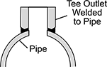
Low-Pressure Iron and Steel Butt-Weld Pipe Fittings
 |
Butt Weld |
Pipe Size | Construction | OD | Pipe Schedule | Material | Each | |||
|---|---|---|---|---|---|---|---|---|
Butt Weld | ||||||||
| 1/2 | Seamless | 27/32" | 40 | Steel | 43425K114 | 000000 | ||
| 3/4 | Seamless | 1 3/64" | 40 | Steel | 43425K124 | 00000 | ||
| 1 | Seamless | 1 5/16" | 40 | Steel | 43425K134 | 00000 | ||
| 1 1/4 | Seamless | 1 21/32" | 40 | Steel | 43425K144 | 00000 | ||
| 1 1/2 | Seamless | 1 29/32" | 40 | Steel | 43425K154 | 00000 | ||
| 2 | Seamless | 2 3/8" | 40 | Steel | 43425K164 | 00000 | ||
| 2 1/2 | Seamless | 2 7/8" | 40 | Steel | 43425K174 | 00000 | ||
| 3 | Seamless | 3 1/2" | 40 | Steel | 43425K184 | 00000 | ||
| 4 | Seamless | 4 1/2" | 40 | Steel | 43425K214 | 000000 | ||
| 6 | Seamless | 6 5/8" | 40 | Steel | 43425K234 | 000000 | ||
| 8 | Seamless | 8 5/8" | 40 | Steel | 43425K244 | 000000 | ||
 |
Pipe Size | Construction | Pipe Schedule | Material | Shape | Each | |||
|---|---|---|---|---|---|---|---|---|
Butt Weld | ||||||||
| 3/4 | Seamless | 40 | Steel | 180° Bend | 43425K123 | 0000000 | ||
| 1 | Seamless | 40 | Steel | 180° Bend | 43425K133 | 000000 | ||
| 1 1/4 | Seamless | 40 | Steel | 180° Bend | 43425K143 | 000000 | ||
| 1 1/2 | Seamless | 40 | Steel | 180° Bend | 43425K153 | 000000 | ||
| 2 | Seamless | 40 | Steel | 180° Bend | 43425K163 | 000000 | ||
| 2 1/2 | Seamless | 40 | Steel | 180° Bend | 43425K173 | 000000 | ||
| 3 | Seamless | 40 | Steel | 180° Bend | 43425K183 | 000000 | ||
| 4 | Seamless | 40 | Steel | 180° Bend | 43425K213 | 000000 | ||
| 6 | Seamless | 40 | Steel | 180° Bend | 43425K233 | 000000 | ||
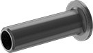 |
Straight Adapter |
Pipe Size | Flange OD | Construction | Pipe Schedule | Finished Material | Each | ||
|---|---|---|---|---|---|---|---|
| 1/2 | 1 3/8" | Seamless | 40 | Steel | 43425K115 | 000000 | |
| 3/4 | 1 11/16" | Seamless | 40 | Steel | 43425K125 | 00000 | |
| 1 | 2" | Seamless | 40 | Steel | 43425K135 | 00000 | |
| 1 1/4 | 2 1/2" | Seamless | 40 | Steel | 43425K145 | 000000 | |
| 1 1/2 | 2 7/8" | Seamless | 40 | Steel | 43425K155 | 000000 | |
| 2 | 3 5/8" | Seamless | 40 | Steel | 43425K165 | 000000 | |
| 2 1/2 | 4 1/8" | Seamless | 40 | Steel | 43425K175 | 000000 | |
| 3 | 5" | Seamless | 40 | Steel | 43425K185 | 000000 | |
| 4 | 6 3/16" | Seamless | 40 | Steel | 43425K215 | 000000 | |
| 6 | 8 1/2" | Seamless | 40 | Steel | 43425K235 | 000000 | |
| 8 | 10 5/8" | Seamless | 40 | Steel | 43425K245 | 000000 |
Medium-Pressure Iron and Steel Threaded Pipe Fittings
 |
NPT Female |
Pipe Size | Pressure Class | Material | Max. Pressure @ Temp. | Max. Steam Pressure @ Temp. | Certification | Each | |||
|---|---|---|---|---|---|---|---|---|---|
NPT Female | |||||||||
| 1/4 | 300 | Iron | 2,000 psi @ 72° F | 300 psi @ 550° F | UL Listed | 4627K251 | 000000 | ||
| 3/8 | 300 | Iron | 2,000 psi @ 72° F | 300 psi @ 550° F | UL Listed | 4627K252 | 00000 | ||
| 1/2 | 300 | Iron | 2,000 psi @ 72° F | 300 psi @ 550° F | UL Listed | 4627K253 | 00000 | ||
| 3/4 | 300 | Iron | 2,000 psi @ 72° F | 300 psi @ 550° F | UL Listed | 4627K254 | 00000 | ||
| 1 | 300 | Iron | 2,000 psi @ 72° F | 300 psi @ 550° F | UL Listed | 4627K255 | 00000 | ||
| 1 1/4 | 300 | Iron | 1,500 psi @ 72° F | 300 psi @ 550° F | UL Listed | 4627K256 | 00000 | ||
| 1 1/2 | 300 | Iron | 1,500 psi @ 72° F | 300 psi @ 550° F | UL Listed | 4627K257 | 00000 | ||
| 2 | 300 | Iron | 1,500 psi @ 72° F | 300 psi @ 550° F | UL Listed | 4627K258 | 00000 | ||
| 2 1/2 | 300 | Iron | 1,000 psi @ 72° F | 300 psi @ 550° F | UL Listed | 4627K359 | 000000 | ||
| 3 | 300 | Iron | 1,000 psi @ 72° F | 300 psi @ 550° F | UL Listed | 4627K361 | 000000 | ||
 |
Threaded NPT Female |
Pipe Size | |||||||||||
|---|---|---|---|---|---|---|---|---|---|---|---|
(A) | (B) | (C) | Pressure Class | Material | Max. Pressure @ Temp. | Max. Steam Pressure @ Temp. | Certification | Each | |||
NPT Female × NPT Female × NPT Female | |||||||||||
| 3/8 | 1/4 | 3/8 | 300 | Iron | 2,000 psi @ 72° F | 300 psi @ 550° F | UL Listed | 4627K362 | 000000 | ||
| 1/2 | 1/4 | 1/2 | 300 | Iron | 2,000 psi @ 72° F | 300 psi @ 550° F | UL Listed | 4627K322 | 00000 | ||
| 1/2 | 3/8 | 1/2 | 300 | Iron | 2,000 psi @ 72° F | 300 psi @ 550° F | UL Listed | 4627K323 | 00000 | ||
| 1/2 | 3/4 | 1/2 | 300 | Iron | 2,000 psi @ 72° F | 300 psi @ 550° F | UL Listed | 4627K364 | 00000 | ||
| 3/4 | 1/4 | 3/4 | 300 | Iron | 2,000 psi @ 72° F | 300 psi @ 550° F | UL Listed | 4627K324 | 00000 | ||
| 3/4 | 3/8 | 3/4 | 300 | Iron | 2,000 psi @ 72° F | 300 psi @ 550° F | UL Listed | 4627K363 | 00000 | ||
| 3/4 | 1/2 | 3/4 | 300 | Iron | 2,000 psi @ 72° F | 300 psi @ 550° F | UL Listed | 4627K325 | 00000 | ||
| 1 | 1/4 | 1 | 300 | Iron | 2,000 psi @ 72° F | 300 psi @ 550° F | UL Listed | 4627K326 | 00000 | ||
| 1 | 1/2 | 1 | 300 | Iron | 2,000 psi @ 72° F | 300 psi @ 550° F | UL Listed | 4627K327 | 00000 | ||
| 1 | 3/4 | 1 | 300 | Iron | 2,000 psi @ 72° F | 300 psi @ 550° F | UL Listed | 4627K328 | 00000 | ||
| 1 1/4 | 1/2 | 1 1/4 | 300 | Iron | 1,500 psi @ 72° F | 300 psi @ 550° F | UL Listed | 4627K365 | 00000 | ||
| 1 1/4 | 3/4 | 1 1/4 | 300 | Iron | 1,500 psi @ 72° F | 300 psi @ 550° F | UL Listed | 4627K329 | 00000 | ||
| 1 1/2 | 1/2 | 1 1/2 | 300 | Iron | 1,500 psi @ 72° F | 300 psi @ 550° F | UL Listed | 4627K369 | 00000 | ||
| 1 1/2 | 3/4 | 1 1/2 | 300 | Iron | 1,500 psi @ 72° F | 300 psi @ 550° F | UL Listed | 4627K368 | 00000 | ||
| 1 1/2 | 1 | 1 1/2 | 300 | Iron | 1,500 psi @ 72° F | 300 psi @ 550° F | UL Listed | 4627K331 | 00000 | ||
| 1 1/2 | 1 1/4 | 1 1/2 | 300 | Iron | 1,500 psi @ 72° F | 300 psi @ 550° F | UL Listed | 4627K366 | 000000 | ||
| 2 | 1/2 | 2 | 300 | Iron | 1,500 psi @ 72° F | 300 psi @ 550° F | UL Listed | 4627K374 | 000000 | ||
| 2 | 3/4 | 2 | 300 | Iron | 1,500 psi @ 72° F | 300 psi @ 550° F | UL Listed | 4627K373 | 000000 | ||
| 2 | 1 | 2 | 300 | Iron | 1,500 psi @ 72° F | 300 psi @ 550° F | UL Listed | 4627K372 | 000000 | ||
| 2 | 1 1/4 | 2 | 300 | Iron | 1,500 psi @ 72° F | 300 psi @ 550° F | UL Listed | 4627K371 | 000000 | ||
| 2 | 1 1/2 | 2 | 300 | Iron | 1,500 psi @ 72° F | 300 psi @ 550° F | UL Listed | 4627K332 | 000000 | ||
| 2 1/2 | 1 1/2 | 2 1/2 | 300 | Iron | 1,000 psi @ 72° F | 300 psi @ 550° F | UL Listed | 4627K375 | 000000 | ||
High-Pressure Iron and Steel Threaded Pipe Fittings
 |
Female |
Pipe Size | Dash Size | Pressure Class | Material | Max. Pressure @ Temp. | Max. Steam Pressure @ Temp. | Each | |||
|---|---|---|---|---|---|---|---|---|---|
NPT Female | |||||||||
| 1/8 | 02 | 3000 | Zinc-Phosphate-Coated Steel | 3,000 psi @ 72° F | 300 psi @ 360° F | 4513K241 | 000000 | ||
| 1/4 | 04 | 3000 | Zinc-Phosphate-Coated Steel | 3,000 psi @ 72° F | 300 psi @ 360° F | 4513K41 | 00000 | ||
| 3/8 | 06 | 3000 | Zinc-Phosphate-Coated Steel | 3,000 psi @ 72° F | 300 psi @ 360° F | 4513K42 | 00000 | ||
| 1/2 | 08 | 3000 | Zinc-Phosphate-Coated Steel | 3,000 psi @ 72° F | 300 psi @ 360° F | 4513K43 | 00000 | ||
| 3/4 | 12 | 3000 | Zinc-Phosphate-Coated Steel | 3,000 psi @ 72° F | 300 psi @ 360° F | 4513K44 | 00000 | ||
| 1 | 16 | 3000 | Zinc-Phosphate-Coated Steel | 3,000 psi @ 72° F | 300 psi @ 360° F | 4513K45 | 00000 | ||
| 1 1/4 | 20 | 3000 | Zinc-Phosphate-Coated Steel | 3,000 psi @ 72° F | 300 psi @ 360° F | 4513K46 | 00000 | ||
| 1 1/2 | 24 | 3000 | Zinc-Phosphate-Coated Steel | 3,000 psi @ 72° F | 300 psi @ 360° F | 4513K47 | 00000 | ||
| 2 | 32 | 3000 | Zinc-Phosphate-Coated Steel | 3,000 psi @ 72° F | 300 psi @ 360° F | 4513K48 | 00000 | ||
| 2 1/2 | 40 | 3000 | Zinc-Phosphate-Coated Steel | 3,000 psi @ 72° F | 300 psi @ 360° F | 4513K242 | 000000 | ||
| 3 | 48 | 3000 | Zinc-Phosphate-Coated Steel | 3,000 psi @ 72° F | 300 psi @ 360° F | 4513K243 | 000000 | ||
| 4 | 64 | 3000 | Zinc-Phosphate-Coated Steel | 3,000 psi @ 72° F | 300 psi @ 360° F | 4513K244 | 000000 | ||
 |
NPT Female × Butt Weld |
Pipe Size (A) | Dash Size (A) | For Pipe Size (B) | Material | Max. Pressure @ Temp. | Max. Steam Pressure @ Temp. | Each | |||
|---|---|---|---|---|---|---|---|---|---|
NPT Female × Butt Weld | |||||||||
| 1/4 | 04 | 1/4 to 3/8 | Zinc-Phosphate-Coated Steel | 3,000 psi @ 72° F | 300 psi @ 360° F | 4587K511 | 000000 | ||
| 1/4 | 04 | 1/2 to 36 | Zinc-Phosphate-Coated Steel | 3,000 psi @ 72° F | 300 psi @ 360° F | 4587K21 | 00000 | ||
| 3/8 | 06 | 3/8 to 1 | Zinc-Phosphate-Coated Steel | 3,000 psi @ 72° F | 300 psi @ 360° F | 4587K521 | 00000 | ||
| 3/8 | 06 | 1 1/4 to 36 | Zinc-Phosphate-Coated Steel | 3,000 psi @ 72° F | 300 psi @ 360° F | 4587K22 | 00000 | ||
| 1/2 | 08 | 1/2 | Zinc-Phosphate-Coated Steel | 3,000 psi @ 72° F | 300 psi @ 360° F | 4587K531 | 00000 | ||
| 1/2 | 08 | 3/4 to 36 | Zinc-Phosphate-Coated Steel | 3,000 psi @ 72° F | 300 psi @ 360° F | 4587K23 | 00000 | ||
| 3/4 | 12 | 3/4 to 1 1/4 | Zinc-Phosphate-Coated Steel | 3,000 psi @ 72° F | 300 psi @ 360° F | 4587K541 | 00000 | ||
| 3/4 | 12 | 1 1/2 to 36 | Zinc-Phosphate-Coated Steel | 3,000 psi @ 72° F | 300 psi @ 360° F | 4587K24 | 00000 | ||
| 1 | 16 | 1 | Zinc-Phosphate-Coated Steel | 3,000 psi @ 72° F | 300 psi @ 360° F | 4587K551 | 00000 | ||
| 1 | 16 | 1 1/4 to 2 1/2 | Zinc-Phosphate-Coated Steel | 3,000 psi @ 72° F | 300 psi @ 360° F | 4587K552 | 00000 | ||
| 1 | 16 | 3 to 36 | Zinc-Phosphate-Coated Steel | 3,000 psi @ 72° F | 300 psi @ 360° F | 4587K25 | 00000 | ||
| 1 1/4 | 20 | 1 1/4 to 1 1/2 | Zinc-Phosphate-Coated Steel | 3,000 psi @ 72° F | 300 psi @ 360° F | 4587K561 | 00000 | ||
| 1 1/4 | 20 | 2 to 3 1/2 | Zinc-Phosphate-Coated Steel | 3,000 psi @ 72° F | 300 psi @ 360° F | 4587K562 | 00000 | ||
| 1 1/4 | 20 | 4 to 36 | Zinc-Phosphate-Coated Steel | 3,000 psi @ 72° F | 300 psi @ 360° F | 4587K26 | 00000 | ||
| 1 1/2 | 24 | 1 1/2 | Zinc-Phosphate-Coated Steel | 3,000 psi @ 72° F | 300 psi @ 360° F | 4587K571 | 00000 | ||
| 1 1/2 | 24 | 2 to 2 1/2 | Zinc-Phosphate-Coated Steel | 3,000 psi @ 72° F | 300 psi @ 360° F | 4587K572 | 00000 | ||
| 1 1/2 | 24 | 3 to 5 | Zinc-Phosphate-Coated Steel | 3,000 psi @ 72° F | 300 psi @ 360° F | 4587K573 | 00000 | ||
| 1 1/2 | 24 | 6 to 36 | Zinc-Phosphate-Coated Steel | 3,000 psi @ 72° F | 300 psi @ 360° F | 4587K27 | 00000 | ||
| 2 | 32 | 2 | Zinc-Phosphate-Coated Steel | 3,000 psi @ 72° F | 300 psi @ 360° F | 4587K581 | 00000 | ||
| 2 | 32 | 2 1/2 to 3 1/2 | Zinc-Phosphate-Coated Steel | 3,000 psi @ 72° F | 300 psi @ 360° F | 4587K582 | 00000 | ||
| 2 | 32 | 4 to 6 | Zinc-Phosphate-Coated Steel | 3,000 psi @ 72° F | 300 psi @ 360° F | 4587K281 | 00000 | ||
| 2 | 32 | 8 to 36 | Zinc-Phosphate-Coated Steel | 3,000 psi @ 72° F | 300 psi @ 360° F | 4587K29 | 00000 | ||
High-Pressure Iron and Steel Socket-Connect Pipe Fittings
 |
Socket Connect |
Pipe Size | Pressure Class | Material | Max. Pressure @ Temp. | Max. Steam Pressure @ Temp. | Each | |||
|---|---|---|---|---|---|---|---|---|
Socket Connect | ||||||||
| 1/8 | 3000 | Steel | 3,000 psi @ 72° F | Not Rated | 45005K151 | 000000 | ||
| 1/4 | 3000 | Steel | 3,000 psi @ 72° F | Not Rated | 45005K152 | 00000 | ||
| 3/8 | 3000 | Steel | 3,000 psi @ 72° F | Not Rated | 45005K153 | 00000 | ||
| 1/2 | 3000 | Steel | 3,000 psi @ 72° F | Not Rated | 45005K154 | 0000 | ||
| 3/4 | 3000 | Steel | 3,000 psi @ 72° F | Not Rated | 45005K155 | 00000 | ||
| 1 | 3000 | Steel | 3,000 psi @ 72° F | Not Rated | 45005K156 | 00000 | ||
| 1 1/4 | 3000 | Steel | 3,000 psi @ 72° F | Not Rated | 45005K157 | 00000 | ||
| 1 1/2 | 3000 | Steel | 3,000 psi @ 72° F | Not Rated | 45005K158 | 00000 | ||
| 2 | 3000 | Steel | 3,000 psi @ 72° F | Not Rated | 45005K159 | 00000 | ||
| 2 1/2 | 3000 | Steel | 3,000 psi @ 72° F | Not Rated | 45005K161 | 00000 | ||
| 3 | 3000 | Steel | 3,000 psi @ 72° F | Not Rated | 45005K162 | 000000 | ||
| 4 | 3000 | Steel | 3,000 psi @ 72° F | Not Rated | 45005K163 | 000000 | ||
 |  |
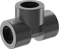
Socket Connect Female × Butt Weld |
Pipe Size (A) | Dash Size (A) | For Pipe Size (B) | Material | Max. Pressure @ Temp. | Max. Steam Pressure @ Temp. | Each | |||
|---|---|---|---|---|---|---|---|---|---|
Socket Connect Female × Butt Weld | |||||||||
| 1/4 | 04 | 3/8 to 36 | Steel | 3,000 psi @ 72° F | 300 psi @ 360° F | 4587K31 | 000000 | ||
| 3/8 | 06 | 3/4 to 36 | Steel | 3,000 psi @ 72° F | 300 psi @ 360° F | 4587K32 | 00000 | ||
| 1/2 | 08 | 3/4 to 36 | Steel | 3,000 psi @ 72° F | 300 psi @ 360° F | 4587K33 | 00000 | ||
| 3/4 | 12 | 3/4 to 1 1/4 | Steel | 3,000 psi @ 72° F | 300 psi @ 360° F | 4587K94 | 00000 | ||
| 3/4 | 12 | 1 1/2 to 36 | Steel | 3,000 psi @ 72° F | 300 psi @ 360° F | 4587K34 | 00000 | ||
| 1 | 16 | 1 | Steel | 3,000 psi @ 72° F | 300 psi @ 360° F | 4587K95 | 00000 | ||
| 1 | 16 | 1 1/4 to 2 1/2 | Steel | 3,000 psi @ 72° F | 300 psi @ 360° F | 4587K75 | 00000 | ||
| 1 | 16 | 3 to 36 | Steel | 3,000 psi @ 72° F | 300 psi @ 360° F | 4587K35 | 00000 | ||
| 1 1/4 | 20 | 1 1/4 to 1 1/2 | Steel | 3,000 psi @ 72° F | 300 psi @ 360° F | 4587K96 | 00000 | ||
| 1 1/4 | 20 | 2 to 3 1/2 | Steel | 3,000 psi @ 72° F | 300 psi @ 360° F | 4587K76 | 00000 | ||
| 1 1/4 | 20 | 4 to 36 | Steel | 3,000 psi @ 72° F | 300 psi @ 360° F | 4587K36 | 00000 | ||
| 1 1/2 | 24 | 1 1/2 | Steel | 3,000 psi @ 72° F | 300 psi @ 360° F | 4587K97 | 00000 | ||
| 1 1/2 | 24 | 2 to 2 1/2 | Steel | 3,000 psi @ 72° F | 300 psi @ 360° F | 4587K77 | 00000 | ||
| 1 1/2 | 24 | 3 to 5 | Steel | 3,000 psi @ 72° F | 300 psi @ 360° F | 4587K87 | 00000 | ||
| 1 1/2 | 24 | 6 to 36 | Steel | 3,000 psi @ 72° F | 300 psi @ 360° F | 4587K37 | 00000 | ||
| 2 | 32 | 2 | Steel | 3,000 psi @ 72° F | 300 psi @ 360° F | 4587K98 | 00000 | ||
| 2 | 32 | 2 1/2 to 3 1/2 | Steel | 3,000 psi @ 72° F | 300 psi @ 360° F | 4587K78 | 00000 | ||
| 2 | 32 | 4 to 6 | Steel | 3,000 psi @ 72° F | 300 psi @ 360° F | 4587K381 | 00000 | ||
| 2 | 32 | 8 to 36 | Steel | 3,000 psi @ 72° F | 300 psi @ 360° F | 4587K88 | 00000 | ||
FM-Approved Low-Pressure Iron and Steel Flanged-End Pipe Fittings
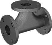 |
Flanged |
Pipe Size | Flange OD | Material | Max. Pressure @ Temp. | Max. Steam Pressure @ Temp. | Mil. Spec. | Certification | Each | |||
|---|---|---|---|---|---|---|---|---|---|---|
Flanged | ||||||||||
| 2 | 6" | Iron | 150 psi @ 72° F | 125 psi @ 350° F | Fed. Spec. WW-F-406 | FM Approved, UL Listed | 1117T24 | 0000000 | ||
| 2 1/2 | 7" | Iron | 150 psi @ 72° F | 125 psi @ 350° F | Fed. Spec. WW-F-406 | FM Approved, UL Listed | 1117T25 | 000000 | ||
| 3 | 7 1/2" | Iron | 150 psi @ 72° F | 125 psi @ 350° F | Fed. Spec. WW-F-406 | FM Approved, UL Listed | 1117T26 | 000000 | ||
| 4 | 9" | Iron | 150 psi @ 72° F | 125 psi @ 350° F | Fed. Spec. WW-F-406 | FM Approved, UL Listed | 1117T27 | 000000 | ||
High-Pressure Iron and Steel Butt-Weld Pipe Fittings
 |
Butt Weld |
Pipe Size | Construction | OD | Pipe Schedule | Material | Each | |||
|---|---|---|---|---|---|---|---|---|
Butt Weld | ||||||||
| 3/4 | Seamless | 1 3/64" | 80 | Steel | 4981T92 | 000000 | ||
| 1 | Seamless | 1 5/16" | 80 | Steel | 4981T93 | 00000 | ||
| 1 1/4 | Seamless | 1 21/32" | 80 | Steel | 4981T94 | 00000 | ||
| 1 1/2 | Seamless | 1 29/32" | 80 | Steel | 4981T95 | 00000 | ||
| 2 | Seamless | 2 3/8" | 80 | Steel | 4981T96 | 00000 | ||
| 2 1/2 | Seamless | 2 7/8" | 80 | Steel | 4981T97 | 00000 | ||
| 3 | Seamless | 3 1/2" | 80 | Steel | 4981T98 | 00000 | ||
| 4 | Seamless | 4 1/2" | 80 | Steel | 4981T99 | 000000 | ||
| 6 | Seamless | 6 5/8" | 80 | Steel | 4981T23 | 000000 | ||
|
Straight Adapter |
Pipe Size | Flange OD | Construction | Pipe Schedule | Finished Material | Each | ||
|---|---|---|---|---|---|---|---|
| 3/4 | 1 1/16" | Seamless | 80 | Steel | 4981T221 | 000000 | |
| 1 | 2" | Seamless | 80 | Steel | 4981T231 | 00000 | |
| 1 1/4 | 2 1/2" | Seamless | 80 | Steel | 4981T241 | 000000 | |
| 1 1/2 | 2 7/8" | Seamless | 80 | Steel | 4981T251 | 000000 | |
| 2 | 3 5/8" | Seamless | 80 | Steel | 4981T261 | 000000 | |
| 2 1/2 | 4 1/8" | Seamless | 80 | Steel | 4981T271 | 000000 | |
| 3 | 5" | Seamless | 80 | Steel | 4981T281 | 000000 | |
| 4 | 6 3/16" | Seamless | 80 | Steel | 4981T291 | 000000 | |
| 6 | 8 1/2" | Seamless | 80 | Steel | 4981T321 | 000000 |
High-Pressure Galvanized Iron and Steel Threaded Pipe Fittings
 |
Female |
Pipe Size | Dash Size | Pressure Class | Material | Max. Pressure @ Temp. | Max. Steam Pressure @ Temp. | Each | |||
|---|---|---|---|---|---|---|---|---|---|
NPT Female | |||||||||
| 1/8 | 02 | 3000 | Galvanized Steel | 3,000 psi @ 72° F | 300 psi @ 360° F | 7739K131 | 000000 | ||
| 1/4 | 04 | 3000 | Galvanized Steel | 3,000 psi @ 72° F | 300 psi @ 360° F | 7739K132 | 00000 | ||
| 3/8 | 06 | 3000 | Galvanized Steel | 3,000 psi @ 72° F | 300 psi @ 360° F | 7739K133 | 00000 | ||
| 1/2 | 08 | 3000 | Galvanized Steel | 3,000 psi @ 72° F | 300 psi @ 360° F | 7739K134 | 00000 | ||
| 3/4 | 12 | 3000 | Galvanized Steel | 3,000 psi @ 72° F | 300 psi @ 360° F | 7739K135 | 00000 | ||
| 1 | 16 | 3000 | Galvanized Steel | 3,000 psi @ 72° F | 300 psi @ 360° F | 7739K136 | 00000 | ||
| 1 1/4 | 20 | 3000 | Galvanized Steel | 3,000 psi @ 72° F | 300 psi @ 360° F | 7739K137 | 00000 | ||
| 1 1/2 | 24 | 3000 | Galvanized Steel | 3,000 psi @ 72° F | 300 psi @ 360° F | 7739K138 | 00000 | ||
| 2 | 32 | 3000 | Galvanized Steel | 3,000 psi @ 72° F | 300 psi @ 360° F | 7739K139 | 00000 | ||
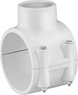
Drain, Waste, and Vent PVC Clamp-On Pipe Fittings for Water
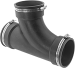 |
Clamp On × Clamp On × Clamp On |
For Pipe Size | For Pipe OD | Material | Max. Pressure @ Temp. | Clamp Material | Certification | Each | |||
|---|---|---|---|---|---|---|---|---|---|
Clamp-On Female for Pipe Ends × Clamp-On Female for Pipe Ends × Clamp-On Female for Pipe Ends | |||||||||
| 1 1/2 | 1 7/8" | PVC | 4 psi @ 72° F | 300 Series Stainless Steel | ICC-ES Listed | 4511K31 | 000000 | ||
| 2 | 2 3/8" | PVC | 4 psi @ 72° F | 300 Series Stainless Steel | ICC-ES Listed | 4511K32 | 00000 | ||
| 3 | 3 1/2" | PVC | 4 psi @ 72° F | 300 Series Stainless Steel | ICC-ES Listed | 4511K33 | 00000 | ||
| 4 | 4 1/2" | PVC | 4 psi @ 72° F | 300 Series Stainless Steel | ICC-ES Listed | 4511K34 | 00000 | ||
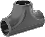
Low-Pressure Iron and Steel Threaded Pipe Fittings with Sealant
 |
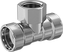
NPT Female × NPT Female × NPT Male |
Extreme-Pressure Iron and Steel Threaded Pipe Fittings
 |
Female |
Pipe Size | Dash Size | Pressure Class | Material | Max. Pressure @ Temp. | Max. Steam Pressure @ Temp. | Each | |||
|---|---|---|---|---|---|---|---|---|---|
NPT Female | |||||||||
| 1/4 | 04 | 6000 | Steel | 6,000 psi @ 72° F | 300 psi @ 360° F | 43455K21 | 000000 | ||
| 3/8 | 06 | 6000 | Steel | 6,000 psi @ 72° F | 300 psi @ 360° F | 43455K22 | 00000 | ||
| 1/2 | 08 | 6000 | Steel | 6,000 psi @ 72° F | 300 psi @ 360° F | 43455K43 | 00000 | ||
| 3/4 | 12 | 6000 | Steel | 6,000 psi @ 72° F | 300 psi @ 360° F | 43455K44 | 00000 | ||
| 1 | 16 | 6000 | Steel | 6,000 psi @ 72° F | 300 psi @ 360° F | 43455K45 | 00000 | ||
| 1 1/4 | 20 | 6000 | Steel | 6,000 psi @ 72° F | 300 psi @ 360° F | 43455K112 | 00000 | ||
| 1 1/2 | 24 | 6000 | Steel | 6,000 psi @ 72° F | 300 psi @ 360° F | 43455K47 | 000000 | ||
| 2 | 32 | 6000 | Steel | 6,000 psi @ 72° F | 300 psi @ 360° F | 43455K48 | 000000 | ||
FM-Approved Low-Pressure Iron and Steel Threaded Pipe Fittings
 |
NPT Female |
Pipe Size | Pressure Class | Material | Max. Pressure @ Temp. | Max. Steam Pressure @ Temp. | Certification | Each | |||
|---|---|---|---|---|---|---|---|---|---|
NPT Female | |||||||||
| 1/2 | 125 | Cast Iron | 125 psi @ 72° F | 125 psi @ 350° F | FM Approved, UL Listed | 68115K41 | 000000 | ||
| 3/4 | 125 | Cast Iron | 125 psi @ 72° F | 125 psi @ 350° F | FM Approved, UL Listed | 68115K42 | 00000 | ||
| 1 | 125 | Cast Iron | 125 psi @ 72° F | 125 psi @ 350° F | FM Approved, UL Listed | 68115K43 | 00000 | ||
| 1 1/4 | 125 | Cast Iron | 125 psi @ 72° F | 125 psi @ 350° F | FM Approved, UL Listed | 68115K44 | 00000 | ||
| 1 1/2 | 125 | Cast Iron | 125 psi @ 72° F | 125 psi @ 350° F | FM Approved, UL Listed | 68115K45 | 00000 | ||
| 2 | 125 | Cast Iron | 125 psi @ 72° F | 125 psi @ 350° F | FM Approved, UL Listed | 68115K46 | 00000 | ||
| 2 1/2 | 125 | Cast Iron | 125 psi @ 72° F | 125 psi @ 350° F | FM Approved, UL Listed | 68115K47 | 00000 | ||
| 3 | 125 | Cast Iron | 125 psi @ 72° F | 125 psi @ 350° F | FM Approved, UL Listed | 68115K48 | 000000 | ||
| 4 | 125 | Cast Iron | 125 psi @ 72° F | 125 psi @ 350° F | FM Approved, UL Listed | 68115K52 | 000000 | ||
 |
NPT Female |
Pipe Size | |||||||||||
|---|---|---|---|---|---|---|---|---|---|---|---|
(A) | (B) | (C) | Pressure Class | Material | Max. Pressure @ Temp. | Max. Steam Pressure @ Temp. | Certification | Each | |||
NPT Female × NPT Female × NPT Female | |||||||||||
| 3/4 | 1/2 | 3/4 | 125 | Cast Iron | 125 psi @ 72° F | 125 psi @ 350° F | FM Approved, UL Listed | 68115K61 | 000000 | ||
| 1 | 1/2 | 1 | 125 | Cast Iron | 125 psi @ 72° F | 125 psi @ 350° F | FM Approved, UL Listed | 68115K65 | 00000 | ||
| 1 | 3/4 | 1 | 125 | Cast Iron | 125 psi @ 72° F | 125 psi @ 350° F | FM Approved, UL Listed | 68115K63 | 00000 | ||
| 1 1/4 | 1/2 | 1 1/4 | 125 | Cast Iron | 125 psi @ 72° F | 125 psi @ 350° F | FM Approved, UL Listed | 68115K68 | 00000 | ||
| 1 1/4 | 3/4 | 1 1/4 | 125 | Cast Iron | 125 psi @ 72° F | 125 psi @ 350° F | FM Approved, UL Listed | 68115K72 | 00000 | ||
| 1 1/4 | 1 | 1 1/4 | 125 | Cast Iron | 125 psi @ 72° F | 125 psi @ 350° F | FM Approved, UL Listed | 68115K69 | 00000 | ||
| 1 1/2 | 1/2 | 1 1/2 | 125 | Cast Iron | 125 psi @ 72° F | 125 psi @ 350° F | FM Approved, UL Listed | 68115K83 | 00000 | ||
| 1 1/2 | 3/4 | 1 1/2 | 125 | Cast Iron | 125 psi @ 72° F | 125 psi @ 350° F | FM Approved, UL Listed | 68115K79 | 00000 | ||
| 1 1/2 | 1 | 1 1/2 | 125 | Cast Iron | 125 psi @ 72° F | 125 psi @ 350° F | FM Approved, UL Listed | 68115K76 | 00000 | ||
| 1 1/2 | 1 1/4 | 1 1/2 | 125 | Cast Iron | 125 psi @ 72° F | 125 psi @ 350° F | FM Approved, UL Listed | 68115K74 | 00000 | ||
| 2 | 1/2 | 2 | 125 | Cast Iron | 125 psi @ 72° F | 125 psi @ 350° F | FM Approved, UL Listed | 68115K96 | 00000 | ||
| 2 | 3/4 | 2 | 125 | Cast Iron | 125 psi @ 72° F | 125 psi @ 350° F | FM Approved, UL Listed | 68115K94 | 00000 | ||
| 2 | 1 | 2 | 125 | Cast Iron | 125 psi @ 72° F | 125 psi @ 350° F | FM Approved, UL Listed | 68115K92 | 00000 | ||
| 2 | 1 1/4 | 2 | 125 | Cast Iron | 125 psi @ 72° F | 125 psi @ 350° F | FM Approved, UL Listed | 68115K89 | 00000 | ||
| 2 | 1 1/2 | 2 | 125 | Cast Iron | 125 psi @ 72° F | 125 psi @ 350° F | FM Approved, UL Listed | 68115K86 | 00000 | ||
Medium-Pressure Galvanized Iron and Steel Threaded Pipe Fittings
 |
Female |
Pipe Size | Pressure Class | Material | Max. Pressure @ Temp. | Max. Steam Pressure @ Temp. | Each | |||
|---|---|---|---|---|---|---|---|---|
NPT Female | ||||||||
| 1/4 | 300 | Galvanized Iron | 2,000 psi @ 72° F | 300 psi @ 550° F | 2066N34 | 000000 | ||
| 3/8 | 300 | Galvanized Iron | 2,000 psi @ 72° F | 300 psi @ 550° F | 2066N35 | 00000 | ||
| 1/2 | 300 | Galvanized Iron | 2,000 psi @ 72° F | 300 psi @ 550° F | 2066N36 | 00000 | ||
| 3/4 | 300 | Galvanized Iron | 2,000 psi @ 72° F | 300 psi @ 550° F | 2066N37 | 00000 | ||
| 1 | 300 | Galvanized Iron | 2,000 psi @ 72° F | 300 psi @ 550° F | 2066N38 | 00000 | ||
| 1 1/4 | 300 | Galvanized Iron | 1,500 psi @ 72° F | 300 psi @ 550° F | 2066N39 | 00000 | ||
| 1 1/2 | 300 | Galvanized Iron | 1,500 psi @ 72° F | 300 psi @ 550° F | 2066N4 | 000000 | ||
| 2 | 300 | Galvanized Iron | 1,500 psi @ 72° F | 300 psi @ 550° F | 2066N41 | 000000 | ||
 |
Female |
Pipe Size | ||||||||||
|---|---|---|---|---|---|---|---|---|---|---|
(A) | (B) | (C) | Pressure Class | Material | Max. Pressure @ Temp. | Max. Steam Pressure @ Temp. | Each | |||
NPT Female × NPT Female × NPT Female | ||||||||||
| 3/4 | 1/2 | 3/4 | 300 | Galvanized Iron | 2,000 psi @ 72° F | 300 psi @ 550° F | 2066N71 | 000000 | ||
| 1 | 1/2 | 1 | 300 | Galvanized Iron | 2,000 psi @ 72° F | 300 psi @ 550° F | 2066N73 | 00000 | ||
| 1 1/4 | 1/2 | 1 1/4 | 300 | Galvanized Iron | 1,500 psi @ 72° F | 300 psi @ 550° F | 2066N76 | 000000 | ||
| 1 1/4 | 3/4 | 1 1/4 | 300 | Galvanized Iron | 1,500 psi @ 72° F | 300 psi @ 550° F | 2066N75 | 000000 | ||
| 1 1/4 | 1 | 1 1/4 | 300 | Galvanized Iron | 1,500 psi @ 72° F | 300 psi @ 550° F | 2066N74 | 000000 | ||
| 1 1/2 | 1/2 | 1 1/2 | 300 | Galvanized Iron | 1,500 psi @ 72° F | 300 psi @ 550° F | 2066N8 | 000000 | ||
| 1 1/2 | 3/4 | 1 1/2 | 300 | Galvanized Iron | 1,500 psi @ 72° F | 300 psi @ 550° F | 2066N79 | 000000 | ||
| 1 1/2 | 1 | 1 1/2 | 300 | Galvanized Iron | 1,500 psi @ 72° F | 300 psi @ 550° F | 2066N78 | 000000 | ||
| 2 | 1/2 | 2 | 300 | Galvanized Iron | 1,500 psi @ 72° F | 300 psi @ 550° F | 2066N85 | 000000 | ||
| 2 | 3/4 | 2 | 300 | Galvanized Iron | 1,500 psi @ 72° F | 300 psi @ 550° F | 2066N84 | 000000 | ||
| 2 | 1 | 2 | 300 | Galvanized Iron | 1,500 psi @ 72° F | 300 psi @ 550° F | 2066N83 | 000000 | ||
| 2 | 1 1/2 | 2 | 300 | Galvanized Iron | 1,500 psi @ 72° F | 300 psi @ 550° F | 2066N81 | 000000 | ||
Medium-Pressure Iron and Steel Butt-Weld Pipe Fittings
 |
Butt Weld × Butt Weld |
Pipe Size (A) | For Pipe Size (B) | Construction | Material | Max. Pressure @ Temp. | Max. Steam Pressure @ Temp. | Each | |||
|---|---|---|---|---|---|---|---|---|---|
Butt Weld × Butt Weld | |||||||||
| 1/4 | 1/2 to 36 | Seamless | Steel | 3,000 psi @ 72° F | 3,000 psi @ 210° F | 1875N12 | 000000 | ||
| 1/2 | 1/2 | Seamless | Steel | 3,000 psi @ 72° F | 3,000 psi @ 210° F | 1875N15 | 00000 | ||
| 1/2 | 3/4 to 36 | Seamless | Steel | 3,000 psi @ 72° F | 3,000 psi @ 210° F | 1875N16 | 00000 | ||
| 3/4 | 3/4 to 1 1/4 | Seamless | Steel | 3,000 psi @ 72° F | 3,000 psi @ 210° F | 1875N17 | 00000 | ||
| 3/4 | 1 1/2 to 36 | Seamless | Steel | 3,000 psi @ 72° F | 3,000 psi @ 210° F | 1875N18 | 00000 | ||
| 1 | 1 | Seamless | Steel | 3,000 psi @ 72° F | 3,000 psi @ 210° F | 1875N19 | 00000 | ||
| 1 | 1 1/4 to 2 1/2 | Seamless | Steel | 3,000 psi @ 72° F | 3,000 psi @ 210° F | 1875N21 | 00000 | ||
| 1 | 3 to 36 | Seamless | Steel | 3,000 psi @ 72° F | 3,000 psi @ 210° F | 1875N22 | 00000 | ||
| 1 1/4 | 2 to 3 1/2 | Seamless | Steel | 3,000 psi @ 72° F | 3,000 psi @ 210° F | 1875N24 | 00000 | ||
| 1 1/4 | 4 to 36 | Seamless | Steel | 3,000 psi @ 72° F | 3,000 psi @ 210° F | 1875N25 | 00000 | ||
| 1 1/2 | 1 1/2 | Seamless | Steel | 2,800 psi @ 72° F | 2,800 psi @ 210° F | 1875N26 | 00000 | ||
| 1 1/2 | 2 to 2 1/2 | Seamless | Steel | 2,800 psi @ 72° F | 2,800 psi @ 210° F | 1875N27 | 00000 | ||
| 1 1/2 | 3 to 5 | Seamless | Steel | 2,800 psi @ 72° F | 2,800 psi @ 210° F | 1875N28 | 00000 | ||
| 2 | 2 | Seamless | Steel | 2,300 psi @ 72° F | 2,300 psi @ 210° F | 1875N31 | 000000 | ||
| 2 | 2 1/2 to 3 1/2 | Seamless | Steel | 2,300 psi @ 72° F | 2,300 psi @ 210° F | 1875N32 | 00000 | ||
| 2 | 4 to 6 | Seamless | Steel | 2,300 psi @ 72° F | 2,300 psi @ 210° F | 1875N33 | 00000 | ||
| 2 | 8 to 36 | Seamless | Steel | 2,300 psi @ 72° F | 2,300 psi @ 210° F | 1875N34 | 00000 | ||
Extreme-Pressure Iron and Steel Socket-Connect Pipe Fittings
 |
Socket Connect |
Pipe Size | Dash Size | Pressure Class | Material | Max. Pressure @ Temp. | Max. Steam Pressure @ Temp. | Each | |||
|---|---|---|---|---|---|---|---|---|---|
Socket Connect | |||||||||
| 1/2 | 08 | 6000 | Steel | 6,000 psi @ 72° F | 300 psi @ 360° F | 43665K154 | 000000 | ||
| 3/4 | 12 | 6000 | Steel | 6,000 psi @ 72° F | 300 psi @ 360° F | 43665K155 | 00000 | ||
| 1 | 16 | 6000 | Steel | 6,000 psi @ 72° F | 300 psi @ 360° F | 43665K156 | 00000 | ||
| 1 1/4 | 20 | 6000 | Steel | 6,000 psi @ 72° F | 300 psi @ 360° F | 43665K157 | 00000 | ||
| 1 1/2 | 24 | 6000 | Steel | 6,000 psi @ 72° F | 300 psi @ 360° F | 43665K158 | 00000 | ||
| 2 | 32 | 6000 | Steel | 6,000 psi @ 72° F | 300 psi @ 360° F | 43665K159 | 00000 | ||
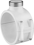
Standard-Wall Plastic Pipe Fittings for Water
 |
Female × Clamp On |
Pipe Size (A) | For Pipe Size (B) | For Pipe OD (B) | For Hole Dia. | OD | Pipe Schedule | Material | Color | Max. Pressure @ Temp. | Gasket Material | Food Industry Std. | Each | |||
|---|---|---|---|---|---|---|---|---|---|---|---|---|---|---|
Cement Socket Female × Clamp On | ||||||||||||||
| 1 1/2 | 3 | 3 1/2" | 2 1/4" | 1 29/32" | 40 | PVC | White | 200 psi @ 72° F | EPDM | NSF/ANSI 61 | 4763K21 | 000000 | ||
| 1 1/2 | 4 | 4 1/2" | 1 3/4" | 1 29/32" | 40 | PVC | White | 200 psi @ 72° F | EPDM | NSF/ANSI 61 | 4763K27 | 000000 | ||
| 2 | 3 | 3 1/2" | 2 1/4" | 2 3/8" | 40 | PVC | White | 200 psi @ 72° F | EPDM | NSF/ANSI 61 | 4763K22 | 00000 | ||
| 2 | 4 | 4 1/2" | 2 1/4" | 2 3/8" | 40 | PVC | White | 200 psi @ 72° F | EPDM | NSF/ANSI 61 | 4763K28 | 000000 | ||
| 2 | 6 | 6 5/8" | 2 1/4" | 2 3/8" | 40 | PVC | White | 200 psi @ 72° F | EPDM | NSF/ANSI 61 | 4763K82 | 000000 | ||
| 3 | 4 | 4 1/2" | 3" | 3 1/2" | 40 | PVC | White | 200 psi @ 72° F | EPDM | NSF/ANSI 61 | 4763K31 | 000000 | ||
 |
Female × Clamp On |
Pipe Size (A) | For Pipe Size (B) | For Pipe OD (B) | For Hole Dia. | OD | Pipe Schedule | Material | Color | Max. Pressure @ Temp. | Gasket Material | Food Industry Std. | Each | |||
|---|---|---|---|---|---|---|---|---|---|---|---|---|---|---|
NPT Female × Clamp On | ||||||||||||||
| 1/2 | 2 | 2 3/8" | 3/4" | 27/32" | 40 | PVC | White | 200 psi @ 72° F | EPDM | NSF/ANSI 61 | 4763K51 | 000000 | ||
| 1/2 | 3 | 3 1/2" | 7/8" | 27/32" | 40 | PVC | White | 300 psi @ 72° F | EPDM | NSF/ANSI 61 | 4763K56 | 000000 | ||
| 1/2 | 4 | 4 1/2" | 1 1/8" | 27/32" | 40 | PVC | White | 300 psi @ 72° F | EPDM | NSF/ANSI 61 | 4763K63 | 000000 | ||
| 3/4 | 2 | 2 3/8" | 7/8" | 1 3/64" | 40 | PVC | White | 200 psi @ 72° F | EPDM | NSF/ANSI 61 | 4763K52 | 00000 | ||
| 3/4 | 3 | 3 1/2" | 7/8" | 1 1/16" | 40 | PVC | White | 240 psi @ 72° F | EPDM | NSF/ANSI 61 | 4763K57 | 000000 | ||
| 3/4 | 4 | 4 1/2" | 1 1/8" | 1 3/64" | 40 | PVC | White | 200 psi @ 72° F | EPDM | NSF/ANSI 61 | 4763K64 | 000000 | ||
| 1 | 2 | 2 3/8" | 1 1/8" | 1 5/16" | 40 | PVC | White | 200 psi @ 72° F | EPDM | NSF/ANSI 61 | 4763K53 | 00000 | ||
| 1 | 3 | 3 1/2" | 1 1/8" | 1 5/16" | 40 | PVC | White | 225 psi @ 72° F | EPDM | NSF/ANSI 61 | 4763K58 | 000000 | ||
| 1 | 4 | 4 1/2" | 1 1/8" | 1 5/16" | 40 | PVC | White | 200 psi @ 72° F | EPDM | NSF/ANSI 61 | 4763K65 | 000000 | ||
| 1 | 6 | 1 5/8" | 1 1/8" | 1 5/16" | 40 | PVC | White | 225 psi @ 72° F | EPDM | NSF/ANSI 61 | 4763K45 | 000000 | ||
| 1 1/2 | 3 | 3 1/2" | 2 1/4" | 1 29/32" | 40 | PVC | White | 165 psi @ 72° F | EPDM | NSF/ANSI 61 | 4763K61 | 000000 | ||
| 1 1/2 | 4 | 4 1/2" | 1 3/4" | 1 29/32" | 40 | PVC | White | 165 psi @ 72° F | EPDM | NSF/ANSI 61 | 4763K67 | 000000 | ||
| 2 | 3 | 3 1/2" | 2 1/4" | 2 3/8" | 40 | PVC | White | 140 psi @ 72° F | EPDM | NSF/ANSI 61 | 4763K46 | 00000 | ||
| 2 | 4 | 4 1/2" | 2" | 2 3/8" | 40 | PVC | White | 140 psi @ 72° F | EPDM | NSF/ANSI 61 | 4763K68 | 000000 | ||
| 2 | 6 | 6 5/8" | 2 1/4" | 2 3/8" | 40 | PVC | White | 200 psi @ 72° F | EPDM | NSF/ANSI 61 | 4763K85 | 000000 | ||
| 3 | 4 | 4 1/2" | 3" | 3 1/2" | 40 | PVC | White | 130 psi @ 72° F | EPDM | NSF/ANSI 61 | 4763K71 | 000000 | ||
Low-Pressure Iron and Steel Press-Socket Pipe Fittings
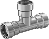 |
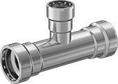
Tee Connector |
Pipe Size | Material | Max. Pressure @ Temp. | O-Ring Material | Certification | Each | |||
|---|---|---|---|---|---|---|---|---|
Press Socket Female | ||||||||
| 1/2 | Zinc-Plated Steel | 125 psi @ 72° F | Buna-N | IAPMO Listed | 3360N164 | 000000 | ||
| 1/2 | Zinc-Plated Steel | 200 psi @ 72° F | EPDM | IAPMO Listed | 3360N158 | 00000 | ||
| 3/4 | Zinc-Plated Steel | 125 psi @ 72° F | Buna-N | IAPMO Listed | 3360N165 | 00000 | ||
| 3/4 | Zinc-Plated Steel | 200 psi @ 72° F | EPDM | IAPMO Listed | 3360N159 | 00000 | ||
| 1 | Zinc-Plated Steel | 125 psi @ 72° F | Buna-N | IAPMO Listed | 3360N166 | 00000 | ||
| 1 | Zinc-Plated Steel | 200 psi @ 72° F | EPDM | IAPMO Listed | 3360N16 | 00000 | ||
| 1 1/4 | Zinc-Plated Steel | 125 psi @ 72° F | Buna-N | IAPMO Listed | 3360N167 | 00000 | ||
| 1 1/4 | Zinc-Plated Steel | 200 psi @ 72° F | EPDM | IAPMO Listed | 3360N161 | 00000 | ||
| 1 1/2 | Zinc-Plated Steel | 125 psi @ 72° F | Buna-N | IAPMO Listed | 3360N168 | 00000 | ||
| 1 1/2 | Zinc-Plated Steel | 200 psi @ 72° F | EPDM | IAPMO Listed | 3360N162 | 00000 | ||
| 2 | Zinc-Plated Steel | 125 psi @ 72° F | Buna-N | IAPMO Listed | 3360N169 | 000000 | ||
| 2 | Zinc-Plated Steel | 200 psi @ 72° F | EPDM | IAPMO Listed | 3360N163 | 000000 | ||
 |
Tee Adapter |
 |
Tee Reducing Adapter |
Pipe Size | ||||||||||
|---|---|---|---|---|---|---|---|---|---|---|
(A) | (B) | (C) | Material | Max. Pressure @ Temp. | O-Ring Material | Certification | Each | |||
Press Socket Female × NPT Female × Press Socket Female | ||||||||||
| 3/4 | 1/2 | 3/4 | Zinc-Plated Steel | 125 psi @ 72° F | Buna-N | IAPMO Listed | 3360N216 | 000000 | ||
| 3/4 | 1/2 | 3/4 | Zinc-Plated Steel | 200 psi @ 72° F | EPDM | IAPMO Listed | 3360N2 | 00000 | ||
| 1 | 1/2 | 1 | Zinc-Plated Steel | 125 psi @ 72° F | Buna-N | IAPMO Listed | 3360N218 | 00000 | ||
| 1 | 1/2 | 1 | Zinc-Plated Steel | 200 psi @ 72° F | EPDM | IAPMO Listed | 3360N202 | 00000 | ||
| 1 | 3/4 | 1 | Zinc-Plated Steel | 125 psi @ 72° F | Buna-N | IAPMO Listed | 3360N219 | 00000 | ||
| 1 | 3/4 | 1 | Zinc-Plated Steel | 200 psi @ 72° F | EPDM | IAPMO Listed | 3360N203 | 00000 | ||
| 2 | 3/4 | 2 | Zinc-Plated Steel | 125 psi @ 72° F | Buna-N | IAPMO Listed | 3360N228 | 000000 | ||
| 2 | 3/4 | 2 | Zinc-Plated Steel | 200 psi @ 72° F | EPDM | IAPMO Listed | 3360N212 | 000000 | ||
| 2 | 1 | 2 | Zinc-Plated Steel | 125 psi @ 72° F | Buna-N | IAPMO Listed | 3360N229 | 000000 | ||
| 2 | 1 | 2 | Zinc-Plated Steel | 200 psi @ 72° F | EPDM | IAPMO Listed | 3360N213 | 000000 | ||
 |
Inline Tee Reducer |
Pipe Size | ||||||||||
|---|---|---|---|---|---|---|---|---|---|---|
(A) | (B) | (C) | Material | Max. Pressure @ Temp. | O-Ring Material | Certification | Each | |||
Press Socket Female × Press Socket Female × Press Socket Female | ||||||||||
| 3/4 | 1/2 | 3/4 | Zinc-Plated Steel | 125 psi @ 72° F | Buna-N | IAPMO Listed | 3360N185 | 000000 | ||
| 3/4 | 1/2 | 3/4 | Zinc-Plated Steel | 200 psi @ 72° F | EPDM | IAPMO Listed | 3360N17 | 00000 | ||
| 1 | 1/2 | 1 | Zinc-Plated Steel | 125 psi @ 72° F | Buna-N | IAPMO Listed | 3360N186 | 00000 | ||
| 1 | 1/2 | 1 | Zinc-Plated Steel | 200 psi @ 72° F | EPDM | IAPMO Listed | 3360N171 | 00000 | ||
| 1 | 3/4 | 1 | Zinc-Plated Steel | 125 psi @ 72° F | Buna-N | IAPMO Listed | 3360N187 | 00000 | ||
| 1 | 3/4 | 1 | Zinc-Plated Steel | 200 psi @ 72° F | EPDM | IAPMO Listed | 3360N172 | 00000 | ||
| 2 | 3/4 | 2 | Zinc-Plated Steel | 125 psi @ 72° F | Buna-N | IAPMO Listed | 3360N196 | 000000 | ||
| 2 | 3/4 | 2 | Zinc-Plated Steel | 200 psi @ 72° F | EPDM | IAPMO Listed | 3360N181 | 000000 | ||
| 2 | 1 | 2 | Zinc-Plated Steel | 125 psi @ 72° F | Buna-N | IAPMO Listed | 3360N197 | 000000 | ||
| 2 | 1 | 2 | Zinc-Plated Steel | 200 psi @ 72° F | EPDM | IAPMO Listed | 3360N182 | 000000 | ||
 |
Battery | ||||||||
|---|---|---|---|---|---|---|---|---|
Voltage, V DC | No. Included | Cap., A·h | Battery Charger Included | Battery Charging Time, min. | Compatible With | Each | ||
| 18 | 2 | 3 | Yes | 39 | Viega MegaPress, Viega ProPress, Viega ProPress XL-C | 2233N106 | 000000000 | |
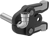 | 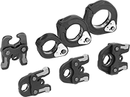 |
Jaw and Ring Set |
For Pipe | |||||||||
|---|---|---|---|---|---|---|---|---|---|
Size | Material | For Mfr. | For Mfr. Model No. | Compatible With | Includes | Container Type | Each | ||
| 1/2, 3/4, 1, 1 1/4, 1 1/2, 2 | Stainless Steel, Steel | Ridgid | RP 340 | Viega MegaPress | One Ring Actuator Jaw, Three Jaws (1/2-1 Pipe Size), Three Rings (1 1/4-2 Pipe Size) | Carrying Case | 2233N318 | 000000000 | |
Thick-Wall Plastic Pipe Fittings for Water
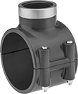 |
Female x Clamp On |
Pipe Size (A) | For Pipe Size (B) | For Pipe OD (B) | For Hole Dia. | Pipe Schedule | Material | Color | Max. Pressure @ Temp. | Gasket Material | Food Industry Std. | Each | |||
|---|---|---|---|---|---|---|---|---|---|---|---|---|---|
NPT Female × Clamp On | |||||||||||||
| 1/2 | 2 | 2 3/8" | 3/4" | 80 | PVC | Dark Gray | 200 psi @ 72° F | EPDM | NSF/ANSI 61 | 4849K51 | 000000 | ||
| 1/2 | 3 | 3 1/2" | 7/8" | 80 | PVC | Dark Gray | 200 psi @ 72° F | EPDM | NSF/ANSI 61 | 4849K56 | 00000 | ||
| 1/2 | 4 | 4 1/2" | 1 1/8" | 80 | PVC | Dark Gray | 200 psi @ 72° F | EPDM | NSF/ANSI 61 | 4849K63 | 000000 | ||
| 3/4 | 2 | 2 3/8" | 7/8" | 80 | PVC | Dark Gray | 200 psi @ 72° F | EPDM | NSF/ANSI 61 | 4849K52 | 00000 | ||
| 3/4 | 3 | 3 1/2" | 7/8" | 80 | PVC | Dark Gray | 200 psi @ 72° F | EPDM | NSF/ANSI 61 | 4849K57 | 00000 | ||
| 3/4 | 4 | 4 1/2" | 1 1/8" | 80 | PVC | Dark Gray | 200 psi @ 72° F | EPDM | NSF/ANSI 61 | 4849K64 | 000000 | ||
| 1 | 2 | 2 3/8" | 1 1/8" | 80 | PVC | Dark Gray | 200 psi @ 72° F | EPDM | NSF/ANSI 61 | 4849K53 | 00000 | ||
| 1 | 3 | 3 1/2" | 1 1/8" | 80 | PVC | Dark Gray | 200 psi @ 72° F | EPDM | NSF/ANSI 61 | 4849K58 | 00000 | ||
| 1 | 4 | 4 1/2" | 1 1/8" | 80 | PVC | Dark Gray | 200 psi @ 72° F | EPDM | NSF/ANSI 61 | 4849K65 | 000000 | ||
| 1 | 6 | 6 5/8" | 1 1/8" | 80 | PVC | Dark Gray | 315 psi @ 72° F | EPDM | NSF/ANSI 61 | 4849K74 | 000000 | ||
| 1 1/2 | 3 | 3 1/2" | 2 1/4" | 80 | PVC | Dark Gray | 200 psi @ 72° F | EPDM | NSF/ANSI 61 | 4849K61 | 00000 | ||
| 1 1/2 | 4 | 4 1/2" | 1 3/4" | 80 | PVC | Dark Gray | 200 psi @ 72° F | EPDM | NSF/ANSI 61 | 4849K67 | 000000 | ||
| 2 | 3 | 3 1/2" | 2 1/4" | 80 | PVC | Dark Gray | 200 psi @ 72° F | EPDM | NSF/ANSI 61 | 4849K62 | 00000 | ||
| 2 | 4 | 4 1/2" | 2 1/4" | 80 | PVC | Dark Gray | 200 psi @ 72° F | EPDM | NSF/ANSI 61 | 4849K68 | 000000 | ||
| 2 | 6 | 6 5/8" | 2 1/4" | 80 | PVC | Dark Gray | 200 psi @ 72° F | EPDM | NSF/ANSI 61 | 4849K82 | 000000 | ||
| 3 | 4 | 4 1/2" | 3" | 80 | PVC | Dark Gray | 185 psi @ 72° F | EPDM | NSF/ANSI 61 | 4849K71 | 000000 | ||
| 3 | 6 | 6 5/8" | 3" | 80 | PVC | Dark Gray | 185 psi @ 72° F | EPDM | NSF/ANSI 61 | 4849K83 | 000000 | ||
