


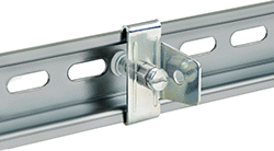
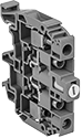
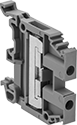
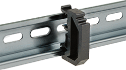
DIN Rail Stops
 |
 |  |  |  |  |
Screw On Rail Stops for DIN 3 Rails | Snap On Rail Stops for DIN 3 Rails | Screw On Rail Stops for DIN 1 or DIN 3 Rails | Screw On Rail Stops for DIN 2 Rails | Screw On Rail Stops for DIN 1 Rails |
Stops | Group Markers | ||||||||||||||
|---|---|---|---|---|---|---|---|---|---|---|---|---|---|---|---|
For DIN Rail | |||||||||||||||
Ht. | Dp. | Ht., mm | Wd., mm | Dp., mm | Material | Color | Flammability Rating | Pkg. Qty. | Pkg. | Pkg. Qty. | Pkg. | ||||
For DIN 3 Rails | |||||||||||||||
Screw On | |||||||||||||||
| 35 mm | 7.5 mm | 39.5 | 16 | 27 | Zinc-Plated Steel | — | — | 10 | 5575N12 | 000000 | 10 | 5575N23 | 00000 | ||
| 35 mm | 7.5 mm, 15 mm | 45 | 8 | 32 | Plastic | Gray | UL 94 V-0 | 10 | 5575N22 | 00000 | 10 | 5575N23 | 0000 | ||
| 35 mm | 7.5 mm, 15 mm | 50 | 9.5 | 44.5 | Plastic | Gray | UL 94 V-0 | 1 | 5575N19 | 0000 | 10 | 5575N23 | 0000 | ||
| 35 mm | 15 mm | 39.5 | 16 | 27 | Zinc-Plated Steel | — | — | 10 | 5575N13 | 00000 | 10 | 5575N23 | 0000 | ||
Snap On | |||||||||||||||
| 35 mm | 7.5 mm, 15 mm | 41 | 6 | 35 | Plastic | Gray | UL 94 V-0 | 5 | 5575N17 | 0000 | 10 | 5575N23 | 0000 | ||
| 35 mm | 15 mm | 41 | 10 | 35 | Plastic | Gray | UL 94 V-0 | 10 | 5575N15 | 00000 | 10 | 5575N23 | 0000 | ||
For DIN 3 or DIN 1 Rails | |||||||||||||||
Screw On | |||||||||||||||
| 35 mm 32 mm | 7.5 mm, 15 mm 15 mm | 44 | 9 | 34 | Plastic | Gray | UL 94 V-0 | 10 | 5575N21 | 00000 | 10 | 5575N23 | 0000 | ||
| 35 mm 32 mm | 7.5 mm, 15 mm 15 mm | 50 | 9 | 46 | Plastic | Gray | UL 94 V-0 | 1 | 5575N18 | 0000 | 10 | 5575N23 | 0000 | ||
For DIN 2 Rails | |||||||||||||||
Screw On | |||||||||||||||
| 15 mm | 5.5 mm | 28 | 8 | 20 | Plastic | Gray | UL 94 V-0 | 10 | 5575N11 | 0000 | 10 | 5575N23 | 0000 | ||
For DIN 1 Rails | |||||||||||||||
Screw On | |||||||||||||||
| 32 mm | 15 mm | 22.5 | 11.5 | 25 | Zinc-Plated Steel | — | — | 10 | 5575N14 | 00000 | 10 | 5575N23 | 0000 | ||
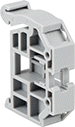
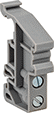
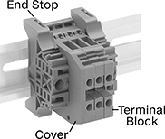
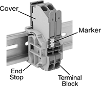
Modular DIN-Rail Mount Terminal Blocks
 |
 |
Terminal Blocks | Covers | End Stops | Bar Jumpers | ||||||||||||||||
|---|---|---|---|---|---|---|---|---|---|---|---|---|---|---|---|---|---|---|---|
Each | |||||||||||||||||||
No. of Circuits | No. of Terminals per Circuit | For Wire Ga. | Wd., mm | Ht., mm | For DIN Rail Trade Size | Enclosure Rating | Choose a Color | 1-24 | 25-Up | Each | Each | Insulation | Each | ||||||
380V AC—22 amp per Circuit | |||||||||||||||||||
| 3 | 2 | 20 to 12 | 6 | 81 | 3 | IP20 | Gray | 7641K361 | 00000 | 00000 | 7641K275 | 00000 | 7641K73 | 00000 | Noninsulated | 7641K281 | 00000 | ||
600V AC—32 amp per Circuit | |||||||||||||||||||
| 1 | 6 | 22 to 12 | 6 | 87.5 | 1, 3 | IP20 | Black | 7641K843 | 00000 | 00000 | ——— | 0 | ——— | 0 | — | ——— | 0 | ||
630V AC/630V DC—24 amp per Circuit | |||||||||||||||||||
| 2 | 2 | 22 to 12 | 5 | 65.5 | 1, 3 | IP20 | Beige | 7641K846 | 0000 | 0000 | 7641K72 | 0000 | 7641K757 | 0000 | Insulated | 7641K758 | 00000 | ||
| 2 | 2 | 22 to 12 | 5 | 65.5 | 1, 3 | IP20 | Blue | 7641K845 | 0000 | 0000 | 7641K72 | 0000 | 7641K757 | 0000 | Insulated | 7641K758 | 00000 | ||
| 2 | 2 | 22 to 12 | 5 | 65.5 | 1, 3 | IP20 | Gray | 7641K844 | 0000 | 0000 | 7641K72 | 0000 | 7641K757 | 0000 | Insulated | 7641K758 | 00000 | ||
800V AC—32 amp per Circuit | |||||||||||||||||||
| 2 | 2 | 22 to 12 | 6 | 65.5 | 1, 3 | IP20 | Beige, Black, Blue, Gray, Green, Orange, Red, White, Yellow | 7641K71 | 0000 | 0000 | 7641K72 | 0000 | 7641K73 | 0000 | Noninsulated | 7641K74 | 00000 | ||
800V AC/800V DC—32 amp per Circuit | |||||||||||||||||||
| 1 | 3 | 22 to 10 | 6 | 51.5 | 1, 3 | IP20 | Gray | 7641K841 | 0000 | 0000 | 7641K754 | 0000 | 7641K35 | 0000 | Insulated | 7641K755 | 00000 | ||
| 1 | 4 | 22 to 10 | 6 | 63.5 | 1, 3 | IP20 | Gray | 7641K842 | 0000 | 0000 | 7641K756 | 0000 | 7641K35 | 0000 | Insulated | 7641K755 | 00000 | ||
800V AC—41 amp per Circuit | |||||||||||||||||||
| 2 | 2 | 18 to 8 | 8 | 88 | 1, 3 | IP20 | Gray | 7641K241 | 0000 | 0000 | 7641K251 | 0000 | 7641K73 | 0000 | Noninsulated | 7641K16 | 00000 | ||
1,000V AC—24 amp per Circuit | |||||||||||||||||||
| 1 | 2 | 22 to 12 | 5 | 44.5 | 1, 3 | IP20 | Beige, Black, Blue, Gray, Orange, Red, White, Yellow | 7641K921 | 0000 | 0000 | 7641K31 | 0000 | 7641K35 | 0000 | Noninsulated | 7641K925 | 00000 | ||
1,000V AC—32 amp per Circuit | |||||||||||||||||||
| 1 | 2 | 22 to 10 | 6 | 44.5 | 1, 3 | IP20 | Beige, Black, Blue, Gray, Green, Orange, Red, White, Yellow | 7641K51 | 0000 | 0000 | 7641K31 | 0000 | 7641K35 | 0000 | Noninsulated | 7641K15 | 00000 | ||
1,000V AC—41 amp per Circuit | |||||||||||||||||||
| 1 | 2 | 22 to 8 | 8 | 44.5 | 1, 3 | IP20 | Beige, Black, Blue, Gray, Green, Orange, Red, White, Yellow | 7641K52 | 0000 | 0000 | 7641K31 | 0000 | 7641K35 | 0000 | Noninsulated | 7641K16 | 00000 | ||
1,000V AC—57 amp per Circuit | |||||||||||||||||||
| 1 | 2 | 20 to 6 | 10 | 44.5 | 1, 3 | IP20 | Beige, Black, Blue, Gray, Red, White, Yellow | 7641K53 | 0000 | 0000 | 7641K31 | 0000 | 7641K35 | 0000 | Noninsulated | 7641K17 | 00000 | ||
1,000V AC—76 amp per Circuit | |||||||||||||||||||
| 1 | 2 | 18 to 6 | 12 | 45.5 | 1, 3 | IP20 | Black, Blue, Gray, Red, White, Yellow | 7641K151 | 0000 | 0000 | 7641K192 | 0000 | 7641K35 | 0000 | Noninsulated | 7641K221 | 00000 | ||
1,000V AC—125 amp per Circuit | |||||||||||||||||||
| 1 | 2 | 10 to 1/0 | 16 | 49 | 1, 3 | IP20 | Black, Blue, Gray, Red, White, Yellow | 7641K161 | 0000 | 0000 | ——— | 0 | 7641K35 | 0000 | Noninsulated | 7641K231 | 00000 | ||
Each | |||||||||
|---|---|---|---|---|---|---|---|---|---|
For No. of Circuits | For Terminal Block Wd., mm | Number Range | Markers per Card | Color | 1-24 | 25-Up | |||
Blank | |||||||||
| 1, 2 | 5 | — | 100 | White | 7641K983 | 00000 | 00000 | ||
| 1, 2 | 6 | — | 100 | White | 7641K19 | 0000 | 0000 | ||
| 1, 2 | 8, 10, 12, 13, 16, 22 | — | 100 | White | 7641K981 | 0000 | 0000 | ||
Numbered for Horizontal Rails | |||||||||
| 1, 2 | 5 | 1 to 100 | 100 | White | 7641K95 | 0000 | 0000 | ||
| 1, 2 | 5 | 101 to 200 | 100 | White | 7641K96 | 0000 | 0000 | ||
| 1, 2 | 6 | 1 to 100 | 100 | White | 7641K75 | 0000 | 0000 | ||
| 1, 2 | 6 | 101 to 200 | 100 | White | 7641K76 | 0000 | 0000 | ||
| 1, 2 | 8, 10, 12, 13, 16, 22 | 1 to 100 | 100 | White | 7641K991 | 0000 | 0000 | ||
| 1, 2 | 8, 10, 12, 13, 16, 22 | 101 to 200 | 100 | White | 7641K992 | 0000 | 0000 | ||
Numbered for Vertical Rails | |||||||||
| 1, 2 | 5 | 1 to 100 | 100 | White | 7641K97 | 0000 | 0000 | ||
| 1, 2 | 5 | 101 to 200 | 100 | White | 7641K98 | 0000 | 0000 | ||
| 1, 2 | 6 | 1 to 100 | 100 | White | 7641K77 | 0000 | 0000 | ||
| 1, 2 | 6 | 101 to 200 | 100 | White | 7641K78 | 0000 | 0000 | ||
| 1, 2 | 8, 10, 12, 13, 16, 22 | 1 to 100 | 100 | White | 7641K993 | 0000 | 0000 | ||
| 1, 2 | 8, 10, 12, 13, 16, 22 | 101 to 200 | 100 | White | 7641K994 | 0000 | 0000 | ||
 |
Terminal Blocks | End Stops | |||||||||||||
|---|---|---|---|---|---|---|---|---|---|---|---|---|---|---|
Each | ||||||||||||||
No. of Circuits | No. of Terminals per Circuit | For Wire Ga. | Wd., mm | Ht., mm | Color | For DIN Rail Trade Size | Enclosure Rating | 1-24 | 25-Up | Each | ||||
| 1 | 2 | 22 to 12 | 5 | 43.5 | Green/Yellow | 1, 3 | IP20 | 7641K931 | 00000 | 00000 | 7641K35 | 00000 | ||
| 1 | 2 | 22 to 12 | 6 | 43.8 | Green/Yellow | 1, 3 | IP20 | 7641K81 | 0000 | 0000 | 7641K35 | 0000 | ||
| 1 | 2 | 22 to 8 | 8 | 43.8 | Green/Yellow | 1, 3 | IP20 | 7641K82 | 0000 | 0000 | 7641K35 | 0000 | ||
| 1 | 2 | 20 to 6 | 10 | 43.8 | Green/Yellow | 1, 3 | IP20 | 7641K83 | 0000 | 0000 | 7641K35 | 0000 | ||
| 1 | 2 | 14 to 4 | 12 | 49.5 | Green/Yellow | 1, 3 | IP20 | 7641K171 | 00000 | 0000 | 7641K35 | 0000 | ||
| 1 | 2 | 8 to 1/0 | 16 | 49 | Green/Yellow | 1, 3 | IP20 | 7641K181 | 00000 | 00000 | 7641K35 | 0000 | ||
| 1 | 4 | 22 to 10 | 6 | 63.5 | Green/Yellow | 1, 3 | IP20 | 7641K847 | 00000 | 0000 | 7641K35 | 0000 | ||
| 1 | 7 | 22 to 12 | 6 | 90 | Green/Yellow | 1, 3 | IP20 | 7641K848 | 00000 | 00000 | 7641K757 | 0000 | ||
Each | |||||||||
|---|---|---|---|---|---|---|---|---|---|
For No. of Circuits | For Terminal Block Wd., mm | Number Range | Markers per Card | Color | 1-24 | 25-Up | |||
Blank | |||||||||
| 1, 2 | 5 | — | 100 | White | 7641K983 | 00000 | 00000 | ||
| 1, 2 | 6 | — | 100 | White | 7641K19 | 0000 | 0000 | ||
| 1, 2 | 8, 10, 12, 13, 16, 22 | — | 100 | White | 7641K981 | 0000 | 0000 | ||
Numbered for Horizontal Rails | |||||||||
| 1, 2 | 5 | 1 to 100 | 100 | White | 7641K95 | 0000 | 0000 | ||
| 1, 2 | 5 | 101 to 200 | 100 | White | 7641K96 | 0000 | 0000 | ||
| 1, 2 | 6 | 1 to 100 | 100 | White | 7641K75 | 0000 | 0000 | ||
| 1, 2 | 6 | 101 to 200 | 100 | White | 7641K76 | 0000 | 0000 | ||
| 1, 2 | 8, 10, 12, 13, 16, 22 | 1 to 100 | 100 | White | 7641K991 | 0000 | 0000 | ||
| 1, 2 | 8, 10, 12, 13, 16, 22 | 101 to 200 | 100 | White | 7641K992 | 0000 | 0000 | ||
Numbered for Vertical Rails | |||||||||
| 1, 2 | 5 | 1 to 100 | 100 | White | 7641K97 | 0000 | 0000 | ||
| 1, 2 | 5 | 101 to 200 | 100 | White | 7641K98 | 0000 | 0000 | ||
| 1, 2 | 6 | 1 to 100 | 100 | White | 7641K77 | 0000 | 0000 | ||
| 1, 2 | 6 | 101 to 200 | 100 | White | 7641K78 | 0000 | 0000 | ||
| 1, 2 | 8, 10, 12, 13, 16, 22 | 1 to 100 | 100 | White | 7641K993 | 0000 | 0000 | ||
| 1, 2 | 8, 10, 12, 13, 16, 22 | 101 to 200 | 100 | White | 7641K994 | 0000 | 0000 | ||
 |
Terminal Blocks | Covers | End Stops | Bar Jumpers | ||||||||||||||||||||||
|---|---|---|---|---|---|---|---|---|---|---|---|---|---|---|---|---|---|---|---|---|---|---|---|---|---|
For Fuse | Each | ||||||||||||||||||||||||
No. of Circuits | No. of Terminals per Circuit | For Wire Ga. | Wd., mm | Ht., mm | Trade Size | Overall Dia. | Overall Lg. | Type | Circuit Status Indicator Type | Blown Fuse Indicator Voltage | For DIN Rail Trade Size | Enclosure Rating | Choose a Color | 1-24 | 25-Up | Each | Each | Insulation | Each | ||||||
300V AC/300V DC—6.3 amp per Circuit | |||||||||||||||||||||||||
| 2 1 (Ground) | 2 1 (Ground) | 20 to 12 | 8 | 99 | — | 5 mm | 20 mm | Ceramic, Glass | — | — | 3 | IP20 | Gray | 7641K861 | 000000 | 000000 | 7641K765 | 00000 | 7641K757 | 00000 | Noninsulated | 7641K16 | 000000 | ||
| 2 1 (Ground) | 2 1 (Ground) | 20 to 12 | 8 | 99 | — | 5 mm | 20 mm | Ceramic, Glass | Blown Fuse | 24V DC 60V DC 110V AC | 3 | IP20 | Gray | 7641K864 | 00000 | 00000 | 7641K765 | 0000 | 7641K757 | 0000 | Noninsulated | 7641K16 | 00000 | ||
| 2 1 (Ground) | 2 1 (Ground) | 20 to 12 | 8 | 99 | — | 5 mm | 20 mm | Ceramic, Glass | Blown Fuse | 110V AC 230V AC | 3 | IP20 | Gray | 7641K865 | 00000 | 00000 | 7641K765 | 0000 | 7641K757 | 0000 | Noninsulated | 7641K16 | 00000 | ||
400V AC/400V DC—6.3 amp per Circuit | |||||||||||||||||||||||||
| 1 | 2 | 22 to 12 | 8 | 56 | — | 5 mm | 20 mm | Ceramic, Glass | Blown Fuse | 24V AC 24V DC | 1, 3 | IP20 | Gray | 7641K943 | 00000 | 00000 | 7641K37 | 0000 | 7641K35 | 0000 | — | ——— | 0 | ||
| 1 | 2 | 22 to 12 | 8 | 56 | — | 5 mm | 20 mm | Ceramic, Glass | Blown Fuse | 110V AC 230V AC | 1, 3 | IP20 | Gray | 7641K942 | 00000 | 00000 | 7641K37 | 0000 | 7641K35 | 0000 | — | ——— | 0 | ||
600V AC—6.3 amp per Circuit | |||||||||||||||||||||||||
| 2 | 2 | 24 to 12 | 8 | 85.5 | — | 5 mm | 20 mm | Ceramic, Glass | Blown Fuse | 110V AC 230V AC | 1, 3 | IP20 | Gray | 7641K863 | 00000 | 00000 | 7641K759 | 0000 | 7641K757 | 0000 | Insulated | 7641K764 | 00000 | ||
| 2 | 2 | 12 | 8 | 85.5 | — | 5 mm | 20 mm | Ceramic, Glass | Blown Fuse | 24V AC 24V DC | 1, 3 | IP20 | Gray | 7641K862 | 00000 | 00000 | 7641K759 | 0000 | 7641K757 | 0000 | Insulated | 7641K764 | 00000 | ||
630V AC—6.3 amp per Circuit | |||||||||||||||||||||||||
| 1 | 2 | 22 to 12 | 8 | 56 | — | 5 mm | 20 mm | Ceramic, Glass | — | — | 1, 3 | IP20 | Gray, Orange | 7641K55 | 0000 | 0000 | 7641K37 | 0000 | 7641K35 | 0000 | — | ——— | 0 | ||
630V AC/630V DC—6.3 amp per Circuit | |||||||||||||||||||||||||
| 2 | 2 | 24 to 12 | 8 | 85.5 | — | 5 mm | 20 mm | Ceramic, Glass | — | — | 1, 3 | IP20 | Gray | 7641K849 | 00000 | 00000 | 7641K759 | 0000 | 7641K757 | 0000 | Insulated | 7641K764 | 00000 | ||
800V AC/800V DC—10 amp per Circuit | |||||||||||||||||||||||||
| 1 | 2 | 22 to 10 | 13 | 85.1 | 3AG | 1/4" | — | Glass | Blown Fuse | 24V AC 24V DC | 1, 3 | IP20 | Black | 7641K946 | 00000 | 00000 | 7641K49 | 0000 | 7641K35 | 0000 | — | ——— | 0 | ||
| 1 | 2 | 22 to 10 | 13 | 85.1 | 3AG | 1/4" | — | Glass | Blown Fuse | 110V AC 230V AC | 1, 3 | IP20 | Black | 7641K945 | 00000 | 00000 | 7641K49 | 0000 | 7641K35 | 0000 | — | ——— | 0 | ||
800V AC—16 amp per Circuit | |||||||||||||||||||||||||
| 1 | 2 | 22 to 10 | 13 | 85.1 | 3AG | 1/4" | — | Glass | — | — | 1, 3 | IP20 | Black | 7641K36 | 00000 | 00000 | 7641K49 | 0000 | 7641K35 | 0000 | — | ——— | 0 | ||
800V AC—30 amp per Circuit | |||||||||||||||||||||||||
| 1 | 2 | 18 to 6 | 22 | 90.7 | — | 13/32" | 1 1/2" | Cartridge | — | — | 1, 3 | IP20 | Gray | 7641K932 | 00000 | 00000 | ——— | 0 | 7641K35 | 0000 | — | ——— | 0 | ||
Blank | Numbered for Horizontal Rails | Numbered for Vertical Rails |
Each | |||||||||
|---|---|---|---|---|---|---|---|---|---|
For No. of Circuits | For Terminal Block Wd., mm | Number Range | Markers per Card | Color | 1-24 | 25-Up | |||
Blank | |||||||||
| 1, 2 | 8, 10, 12, 13, 16, 22 | — | 100 | White | 7641K981 | 00000 | 00000 | ||
Numbered for Horizontal Rails | |||||||||
| 1, 2 | 8, 10, 12, 13, 16, 22 | 1 to 100 | 100 | White | 7641K991 | 0000 | 0000 | ||
| 1, 2 | 8, 10, 12, 13, 16, 22 | 101 to 200 | 100 | White | 7641K992 | 0000 | 0000 | ||
Numbered for Vertical Rails | |||||||||
| 1, 2 | 8, 10, 12, 13, 16, 22 | 1 to 100 | 100 | White | 7641K993 | 0000 | 0000 | ||
| 1, 2 | 8, 10, 12, 13, 16, 22 | 101 to 200 | 100 | White | 7641K994 | 0000 | 0000 | ||
 |
Terminal Blocks | Covers | End Stops | Adjacent Jumpers | ||||||||||||||||
|---|---|---|---|---|---|---|---|---|---|---|---|---|---|---|---|---|---|---|---|
Each | |||||||||||||||||||
No. of Circuits | No. of Terminals per Circuit | For Wire Ga. | Wd., mm | Ht., mm | Color | For DIN Rail Trade Size | Enclosure Rating | 1-24 | 25-Up | Each | Each | Insulation | Each | ||||||
320V AC/320V DC—10 amp per Circuit | |||||||||||||||||||
| 1 | 2 | 12 | 5 | 44.5 | Gray/Orange | 1, 3 | IP20 | 7641K869 | 00000 | 00000 | 7641K31 | 00000 | 7641K35 | 00000 | Noninsulated | 7641K767 | 00000 | ||
400V AC—15 amp per Circuit | |||||||||||||||||||
| 1 | 2 | 22 to 10 | 8 | 47 | Gray | 1, 3 | IP20 | 7641K88 | 0000 | 0000 | 7641K881 | 0000 | 7641K35 | 0000 | Insulated | 7641K873 | 0000 | ||
400V AC—20 amp per Circuit | |||||||||||||||||||
| 1 | 2 | 22 to 10 | 6 | 44.5 | Gray | 1, 3 | IP20 | 7641K87 | 0000 | 0000 | 7641K871 | 0000 | 7641K35 | 0000 | Insulated | 7641K883 | 0000 | ||
Each | |||||||||
|---|---|---|---|---|---|---|---|---|---|
For No. of Circuits | For Terminal Block Wd., mm | Number Range | Markers per Card | Color | 1-24 | 25-Up | |||
Blank | |||||||||
| 1, 2 | 5 | — | 100 | White | 7641K983 | 00000 | 00000 | ||
| 1, 2 | 6 | — | 100 | White | 7641K19 | 0000 | 0000 | ||
| 1, 2 | 8, 10, 12, 13, 16, 22 | — | 100 | White | 7641K981 | 0000 | 0000 | ||
Numbered for Horizontal Rails | |||||||||
| 1, 2 | 5 | 1 to 100 | 100 | White | 7641K95 | 0000 | 0000 | ||
| 1, 2 | 5 | 101 to 200 | 100 | White | 7641K96 | 0000 | 0000 | ||
| 1, 2 | 6 | 1 to 100 | 100 | White | 7641K75 | 0000 | 0000 | ||
| 1, 2 | 6 | 101 to 200 | 100 | White | 7641K76 | 0000 | 0000 | ||
| 1, 2 | 8, 10, 12, 13, 16, 22 | 1 to 100 | 100 | White | 7641K991 | 0000 | 0000 | ||
| 1, 2 | 8, 10, 12, 13, 16, 22 | 101 to 200 | 100 | White | 7641K992 | 0000 | 0000 | ||
Numbered for Vertical Rails | |||||||||
| 1, 2 | 5 | 1 to 100 | 100 | White | 7641K97 | 0000 | 0000 | ||
| 1, 2 | 5 | 101 to 200 | 100 | White | 7641K98 | 0000 | 0000 | ||
| 1, 2 | 6 | 1 to 100 | 100 | White | 7641K77 | 0000 | 0000 | ||
| 1, 2 | 6 | 101 to 200 | 100 | White | 7641K78 | 0000 | 0000 | ||
| 1, 2 | 8, 10, 12, 13, 16, 22 | 1 to 100 | 100 | White | 7641K993 | 0000 | 0000 | ||
| 1, 2 | 8, 10, 12, 13, 16, 22 | 101 to 200 | 100 | White | 7641K994 | 0000 | 0000 | ||
 |
Terminal Blocks | Covers | End Stops | Adjacent Jumpers | Test Plugs | |||||||||||||||||
|---|---|---|---|---|---|---|---|---|---|---|---|---|---|---|---|---|---|---|---|---|---|
Each | |||||||||||||||||||||
No. of Circuits | No. of Terminals per Circuit | For Wire Ga. | Wd., mm | Ht., mm | Color | For DIN Rail Trade Size | Enclosure Rating | 1-24 | 25-Up | Each | Each | Insulation | Each | Each | |||||||
500V AC/500V DC—15 amp per Circuit | |||||||||||||||||||||
| 1 | 2 | 22 to 8 | 8 | 55.5 | Gray/Black | 1, 3 | IP10 | 7641K867 | 00000 | 00000 | 7641K766 | 00000 | 7641K35 | 00000 | Insulated | 7641K873 | 00000 | 7641K768 | 00000 | ||
| 1 | 2 | 22 to 8 | 8 | 55.5 | Gray/Red | 1, 3 | IP10 | 7641K868 | 0000 | 0000 | 7641K766 | 0000 | 7641K35 | 0000 | Insulated | 7641K873 | 0000 | 7641K768 | 0000 | ||
| 1 | 2 | 22 to 8 | 8 | 55.5 | Gray/Yellow | 1, 3 | IP10 | 7641K866 | 0000 | 0000 | 7641K766 | 0000 | 7641K35 | 0000 | Insulated | 7641K873 | 0000 | 7641K768 | 0000 | ||
Blank | Numbered for Horizontal Rails | Numbered for Vertical Rails |
Each | |||||||||
|---|---|---|---|---|---|---|---|---|---|
For No. of Circuits | For Terminal Block Wd., mm | Number Range | Markers per Card | Color | 1-24 | 25-Up | |||
Blank | |||||||||
| 1, 2 | 8, 10, 12, 13, 16, 22 | — | 100 | White | 7641K981 | 00000 | 00000 | ||
Numbered for Horizontal Rails | |||||||||
| 1, 2 | 8, 10, 12, 13, 16, 22 | 1 to 100 | 100 | White | 7641K991 | 0000 | 0000 | ||
| 1, 2 | 8, 10, 12, 13, 16, 22 | 101 to 200 | 100 | White | 7641K992 | 0000 | 0000 | ||
Numbered for Vertical Rails | |||||||||
| 1, 2 | 8, 10, 12, 13, 16, 22 | 1 to 100 | 100 | White | 7641K993 | 0000 | 0000 | ||
| 1, 2 | 8, 10, 12, 13, 16, 22 | 101 to 200 | 100 | White | 7641K994 | 0000 | 0000 | ||
 |
Terminal Blocks | Covers | End Stops | |||||||||||||||
|---|---|---|---|---|---|---|---|---|---|---|---|---|---|---|---|---|---|
Each | |||||||||||||||||
No. of Circuits | No. of Terminals per Circuit | For Wire Ga. | Wd., mm | Ht., mm | For Thermocouple Type | Color | For DIN Rail Trade Size | Enclosure Rating | 1-24 | 25-Up | Each | Each | |||||
500V AC/500V DC | |||||||||||||||||
| 1 | 2 | 18 to 16 | 6 | 44.5 | J, K, T | Gray | 1, 3 | IP20 | 7641K381 | 000000 | 000000 | 7641K31 | 00000 | 7641K35 | 00000 | ||
Blank | Numbered for Horizontal Rails | Numbered for Vertical Rails |
Each | |||||||||
|---|---|---|---|---|---|---|---|---|---|
For No. of Circuits | For Terminal Block Wd., mm | Number Range | Markers per Card | Color | 1-24 | 25-Up | |||
Blank | |||||||||
| 1, 2 | 6 | — | 100 | White | 7641K19 | 00000 | 00000 | ||
Numbered for Horizontal Rails | |||||||||
| 1, 2 | 6 | 1 to 100 | 100 | White | 7641K75 | 0000 | 0000 | ||
| 1, 2 | 6 | 101 to 200 | 100 | White | 7641K76 | 0000 | 0000 | ||
Numbered for Vertical Rails | |||||||||
| 1, 2 | 6 | 1 to 100 | 100 | White | 7641K77 | 0000 | 0000 | ||
| 1, 2 | 6 | 101 to 200 | 100 | White | 7641K78 | 0000 | 0000 | ||
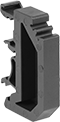
DIN Rail Spacers
 |  |
For DIN Rail | ||||||||||||
|---|---|---|---|---|---|---|---|---|---|---|---|---|
Ht. | Dp. | Ht., mm | Wd., mm | Dp., mm | Material | Color | Flammability Rating | Pkg. Qty. | Pkg. | |||
For DIN 3 or DIN 1 Rails | ||||||||||||
Snap On | ||||||||||||
| 35 mm 32 mm | 7.5 mm, 15 mm 15 mm | 43 | 8 | 29 | Plastic | Black | UL 94 V-0 | 10 | 5575N16 | 00000 | ||
Quick-Connect Modular DIN-Rail Mount Terminal Blocks
 |
Terminal Blocks | Covers | End Stops | Adjacent Jumpers | Alternate Jumpers | |||||||||||||||||
|---|---|---|---|---|---|---|---|---|---|---|---|---|---|---|---|---|---|---|---|---|---|
Each | |||||||||||||||||||||
No. of Circuits | No. of Terminals per Circuit | For Wire Ga. | Wd., mm | Ht., mm | For DIN Rail Trade Size | Choose a Color | 1-24 | 25-Up | Each | Each | Insulation | Each | Insulation | Each | |||||||
300V AC/300V DC—15 amp per Circuit | |||||||||||||||||||||
| 2 | 2 | 28 to 12 | 5 | 64 | 3 | Blue, Gray | 9473T151 | 00000 | 00000 | 9473T154 | 00000 | 9473T144 | 00000 | Insulated | 9473T112 | 00000 | Insulated | 9473T113 | 00000 | ||
| 3 | 2 | 28 to 12 | 5 | 103 | 3 | Blue, Gray | 9473T162 | 00000 | 00000 | 9473T165 | 0000 | 9473T144 | 0000 | Insulated | 9473T112 | 0000 | Insulated | 9473T113 | 0000 | ||
600V AC/600V DC—15 amp per Circuit | |||||||||||||||||||||
| 1 | 2 | 22 to 14 | 4.2 | 48.5 | 3 | Black, Blue, Gray, Orange, Red, Yellow | 9473T173 | 0000 | 0000 | 9473T191 | 0000 | 9473T144 | 0000 | Insulated | 9473T193 | 0000 | Insulated | 9473T194 | 0000 | ||
| 1 | 3 | 22 to 14 | 4.2 | 59.5 | 3 | Black, Blue, Gray, Orange, Red, Yellow | 9473T177 | 0000 | 0000 | 9473T192 | 0000 | 9473T144 | 0000 | Insulated | 9473T193 | 0000 | Insulated | 9473T194 | 0000 | ||
| 1 | 4 | 22 to 14 | 4.2 | 70 | 3 | Black, Blue, Gray, Orange, Red, Yellow | 9473T182 | 0000 | 0000 | 9473T195 | 0000 | 9473T144 | 0000 | Insulated | 9473T193 | 0000 | Insulated | 9473T194 | 0000 | ||
600V AC/600V DC—20 amp per Circuit | |||||||||||||||||||||
| 1 | 2 | 28 to 12 | 5 | 53 | 3 | Black, Blue, Gray, Orange, Red, Yellow | 9473T1 | 0000 | 0000 | 9473T131 | 0000 | 9473T144 | 0000 | Insulated | 9473T112 | 0000 | Insulated | 9473T113 | 0000 | ||
| 1 | 2 | 28 to 12 | 6 | 59 | 3 | Black, Blue, Gray, Orange, Red, Yellow | 9473T24 | 0000 | 0000 | 9473T134 | 0000 | 9473T144 | 0000 | Insulated | 9473T115 | 0000 | Insulated | 9473T116 | 0000 | ||
| 1 | 3 | 28 to 12 | 5 | 64 | 3 | Black, Blue, Gray, Orange, Red, Yellow | 9473T8 | 0000 | 0000 | 9473T132 | 0000 | 9473T144 | 0000 | Insulated | 9473T112 | 0000 | Insulated | 9473T113 | 0000 | ||
| 1 | 3 | 28 to 12 | 6 | 73.5 | 3 | Black, Blue, Gray, Orange, Red, Yellow | 9473T32 | 0000 | 0000 | 9473T135 | 0000 | 9473T144 | 0000 | Insulated | 9473T115 | 0000 | Insulated | 9473T116 | 0000 | ||
| 1 | 4 | 28 to 12 | 5 | 75 | 3 | Black, Blue, Gray, Orange, Red, Yellow | 9473T16 | 0000 | 0000 | 9473T133 | 0000 | 9473T144 | 0000 | Insulated | 9473T112 | 0000 | Insulated | 9473T113 | 0000 | ||
| 1 | 4 | 28 to 12 | 6 | 86 | 3 | Black, Blue, Gray, Orange, Red, Yellow | 9473T39 | 0000 | 0000 | 9473T136 | 0000 | 9473T144 | 0000 | Insulated | 9473T115 | 0000 | Insulated | 9473T116 | 0000 | ||
| 2 | 2 | 28 to 12 | 6 | 73.5 | 3 | Blue, Gray | 9473T157 | 00000 | 0000 | 9473T161 | 0000 | 9473T144 | 0000 | Insulated | 9473T115 | 0000 | Insulated | 9473T116 | 0000 | ||
600V AC/600V DC—30 amp per Circuit | |||||||||||||||||||||
| 1 | 2 | 24 to 10 | 8 | 74.5 | 3 | Blue, Gray, Orange | 9473T47 | 0000 | 0000 | 9473T137 | 0000 | 9473T144 | 0000 | Insulated | 9473T118 | 0000 | Insulated | 9473T119 | 0000 | ||
| 1 | 3 | 24 to 10 | 8 | 93 | 3 | Blue, Gray, Orange | 9473T52 | 0000 | 0000 | 9473T138 | 0000 | 9473T144 | 0000 | Insulated | 9473T118 | 0000 | Insulated | 9473T119 | 0000 | ||
600V AC/600V DC—50 amp per Circuit | |||||||||||||||||||||
| 1 | 2 | 24 to 8 | 10 | 78 | 3 | Blue, Gray, Orange | 9473T56 | 0000 | 0000 | 9473T139 | 0000 | 9473T144 | 0000 | Insulated | 9473T122 | 0000 | Insulated | 9473T123 | 0000 | ||
| 1 | 3 | 24 to 8 | 10 | 97.5 | 3 | Blue, Gray, Orange | 9473T61 | 00000 | 00000 | 9473T141 | 0000 | 9473T144 | 0000 | Insulated | 9473T122 | 0000 | Insulated | 9473T123 | 0000 | ||
600V AC/600V DC—65 amp per Circuit | |||||||||||||||||||||
| 1 | 2 | 24 to 6 | 12 | 94.5 | 3 | Blue, Gray, Orange | 9473T65 | 00000 | 0000 | 9473T142 | 0000 | 9473T144 | 0000 | Insulated | 9473T125 | 0000 | Insulated | 9473T126 | 0000 | ||
| 1 | 3 | 24 to 6 | 12 | 104.5 | 3 | Blue, Gray, Orange | 9473T69 | 00000 | 00000 | 9473T143 | 0000 | 9473T144 | 0000 | — | ——— | 0 | Insulated | 9473T126 | 0000 | ||
600V AC/600V DC—115 amp per Circuit | |||||||||||||||||||||
| 1 | 2 | 8 to 2 | 16 | 100 | 3 | Blue, Gray | 9473T74 | 00000 | 00000 | ——— | 0 | 9473T144 | 0000 | Insulated | 9473T128 | 0000 | — | ——— | 0 | ||
600V AC/600V DC—200 amp per Circuit | |||||||||||||||||||||
| 1 | 2 | 4 to 4/0 | 25 | 107 | 3 | Blue, Gray | 9473T77 | 00000 | 00000 | ——— | 0 | 9473T144 | 0000 | Insulated | 9473T129 | 00000 | — | ——— | 0 | ||
Blank | Numbered for Horizontal Rails | Numbered for Vertical Rails |
Each | |||||||||
|---|---|---|---|---|---|---|---|---|---|
For Terminal Block Wd., mm | Number Range | Includes | Markers per Card | Color | 1-24 | 25-Up | |||
Blank | |||||||||
| 4.2 | — | — | 100 | White | 9473T217 | 00000 | 00000 | ||
| 5, 6, 8, 10, 12, 16, 25 | — | — | 100 | White | 9473T145 | 0000 | 0000 | ||
Numbered for Horizontal Rails | |||||||||
| 4.2 | 1 to 50 | Two of Each Number | 100 | White | 9473T218 | 00000 | 0000 | ||
| 5, 6, 8, 10, 12, 16, 25 | 1 to 50 | Two of Each Number | 100 | White | 9473T146 | 00000 | 0000 | ||
Numbered for Vertical Rails | |||||||||
| 4.2 | 1 to 50 | Two of Each Number | 100 | White | 9473T219 | 00000 | 00000 | ||
| 5, 6, 8, 10, 12, 16, 25 | 1 to 50 | Two of Each Number | 100 | White | 9473T147 | 00000 | 00000 | ||
Terminal Blocks | Covers | End Stops | Adjacent Jumpers | |||||||||||||||
|---|---|---|---|---|---|---|---|---|---|---|---|---|---|---|---|---|---|---|
Each | ||||||||||||||||||
No. of Circuits | No. of Terminals per Circuit | For Wire Ga. | Wd., mm | Ht., mm | Color | For DIN Rail Trade Size | 1-24 | 25-Up | Each | Each | Insulation | Each | ||||||
600V AC/600V DC—5 amp per Circuit | ||||||||||||||||||
| 1 | 1 (Lever Clamp) 1 (Spring Clamp) | 20 to 8 | 7.5 | 74.8 | Blue | 3 | 4036N25 | 00000 | 00000 | 4036N205 | 00000 | 9473T144 | 00000 | Insulated | 4036N303 | 00000 | ||
| 1 | 1 (Lever Clamp) 1 (Spring Clamp) | 20 to 8 | 7.5 | 74.8 | Gray | 3 | 4036N24 | 0000 | 0000 | 4036N205 | 0000 | 9473T144 | 0000 | Insulated | 4036N303 | 0000 | ||
| 1 | 1 (Lever Clamp) 2 (Spring Clamp) | 20 to 8 | 7.5 | 90.8 | Blue | 3 | 4036N28 | 0000 | 0000 | 4036N206 | 0000 | 9473T144 | 0000 | Insulated | 4036N303 | 0000 | ||
| 1 | 1 (Lever Clamp) 2 (Spring Clamp) | 20 to 8 | 7.5 | 90.8 | Gray | 3 | 4036N27 | 0000 | 0000 | 4036N206 | 0000 | 9473T144 | 0000 | Insulated | 4036N303 | 0000 | ||
600V AC/600V DC—20 amp per Circuit | ||||||||||||||||||
| 1 | 1 (Lever Clamp) 1 (Spring Clamp) | 22 to 12 | 5.2 | 61.5 | Blue | 3 | 4036N12 | 0000 | 0000 | 4036N201 | 0000 | 9473T144 | 0000 | Insulated | 4036N301 | 0000 | ||
| 1 | 1 (Lever Clamp) 1 (Spring Clamp) | 22 to 12 | 5.2 | 61.5 | Gray | 3 | 4036N11 | 0000 | 0000 | 4036N201 | 0000 | 9473T144 | 0000 | Insulated | 4036N301 | 0000 | ||
| 1 | 1 (Lever Clamp) 2 (Spring Clamp) | 22 to 12 | 5.2 | 72.2 | Blue | 3 | 4036N15 | 0000 | 0000 | 4036N202 | 0000 | 9473T144 | 0000 | Insulated | 4036N301 | 0000 | ||
| 1 | 1 (Lever Clamp) 2 (Spring Clamp) | 22 to 12 | 5.2 | 72.2 | Gray | 3 | 4036N14 | 0000 | 0000 | 4036N202 | 0000 | 9473T144 | 0000 | Insulated | 4036N301 | 0000 | ||
600V AC/600V DC—30 amp per Circuit | ||||||||||||||||||
| 1 | 1 (Lever Clamp) 1 (Spring Clamp) | 20 to 10 | 6.2 | 70 | Blue | 3 | 4036N18 | 0000 | 0000 | 4036N203 | 0000 | 9473T144 | 0000 | Insulated | 4036N302 | 0000 | ||
| 1 | 1 (Lever Clamp) 1 (Spring Clamp) | 20 to 10 | 6.2 | 70 | Gray | 3 | 4036N17 | 0000 | 0000 | 4036N203 | 0000 | 9473T144 | 0000 | Insulated | 4036N302 | 0000 | ||
| 1 | 1 (Lever Clamp) 2 (Spring Clamp) | 20 to 10 | 6.2 | 83.2 | Blue | 3 | 4036N22 | 0000 | 0000 | 4036N204 | 0000 | 9473T144 | 0000 | Insulated | 4036N302 | 0000 | ||
| 1 | 1 (Lever Clamp) 2 (Spring Clamp) | 20 to 10 | 6.2 | 83.2 | Gray | 3 | 4036N21 | 0000 | 0000 | 4036N204 | 0000 | 9473T144 | 0000 | Insulated | 4036N302 | 0000 | ||
600V AC/600V DC—65 amp per Circuit | ||||||||||||||||||
| 1 | 1 (Lever Clamp) 1 (Spring Clamp) | 20 to 6 | 10 | 89 | Blue | 3 | 4036N32 | 0000 | 0000 | 4036N207 | 0000 | 9473T144 | 0000 | Insulated | 4036N304 | 0000 | ||
| 1 | 1 (Lever Clamp) 1 (Spring Clamp) | 20 to 6 | 10 | 89 | Gray | 3 | 4036N31 | 0000 | 0000 | 4036N207 | 0000 | 9473T144 | 0000 | Insulated | 4036N304 | 0000 | ||
| 1 | 1 (Lever Clamp) 2 (Spring Clamp) | 20 to 6 | 10 | 110.4 | Blue | 3 | 4036N35 | 00000 | 00000 | 4036N208 | 0000 | 9473T144 | 0000 | Insulated | 4036N304 | 0000 | ||
| 1 | 1 (Lever Clamp) 2 (Spring Clamp) | 20 to 6 | 10 | 110.4 | Gray | 3 | 4036N34 | 00000 | 00000 | 4036N208 | 0000 | 9473T144 | 0000 | Insulated | 4036N304 | 0000 | ||
600V AC/600V DC—85 amp per Circuit | ||||||||||||||||||
| 1 | 1 (Lever Clamp) 1 (Spring Clamp) | 20 to 6 | 12 | 91.5 | Blue | 3 | 4036N38 | 0000 | 0000 | 4036N209 | 0000 | 9473T144 | 0000 | Insulated | 4036N305 | 0000 | ||
| 1 | 1 (Lever Clamp) 1 (Spring Clamp) | 20 to 6 | 12 | 91.5 | Gray | 3 | 4036N37 | 0000 | 0000 | 4036N209 | 0000 | 9473T144 | 0000 | Insulated | 4036N305 | 0000 | ||
| 1 | 1 (Lever Clamp) 2 (Spring Clamp) | 20 to 6 | 12 | 113.5 | Blue | 3 | 4036N42 | 00000 | 00000 | 4036N211 | 0000 | 9473T144 | 0000 | Insulated | 4036N305 | 0000 | ||
| 1 | 1 (Lever Clamp) 2 (Spring Clamp) | 20 to 6 | 12 | 113.5 | Gray | 3 | 4036N41 | 00000 | 00000 | 4036N211 | 0000 | 9473T144 | 0000 | Insulated | 4036N305 | 0000 | ||
Blank |
For Terminal Block Wd., mm | Markers per Card | Color | Each | |||
|---|---|---|---|---|---|---|
Blank | ||||||
| 5.2, 6.2, 7.5, 10, 12 | 100 | White | 4036N401 | 00000 | ||
Terminal Blocks | Covers | End Stops | Adjacent Jumpers | |||||||||||||||
|---|---|---|---|---|---|---|---|---|---|---|---|---|---|---|---|---|---|---|
Each | ||||||||||||||||||
No. of Circuits | No. of Terminals per Circuit | For Wire Ga. | Wd., mm | Ht., mm | Color | For DIN Rail Trade Size | 1-24 | 25-Up | Each | Each | Insulation | Each | ||||||
| 1 | 2 | 28 to 12 | 5 | 53 | Green/Yellow | 3 | 9473T82 | 000000 | 000000 | 9473T131 | 00000 | 9473T144 | 00000 | Insulated | 9473T114 | 00000 | ||
| 1 | 2 | 28 to 12 | 6 | 59 | Green/Yellow | 3 | 9473T86 | 00000 | 00000 | 9473T134 | 0000 | 9473T144 | 0000 | Insulated | 9473T117 | 0000 | ||
| 1 | 2 | 24 to 10 | 8 | 74.5 | Green/Yellow | 3 | 9473T91 | 00000 | 00000 | 9473T137 | 0000 | 9473T144 | 0000 | Insulated | 9473T121 | 0000 | ||
| 1 | 2 | 24 to 8 | 10 | 78 | Green/Yellow | 3 | 9473T94 | 00000 | 00000 | 9473T139 | 0000 | 9473T144 | 0000 | Insulated | 9473T124 | 0000 | ||
| 1 | 2 | 24 to 6 | 12 | 94.5 | Green/Yellow | 3 | 9473T97 | 00000 | 00000 | 9473T142 | 0000 | 9473T144 | 0000 | Insulated | 9473T127 | 0000 | ||
| 1 | 2 | 22 to 14 | 4.2 | 50.8 | Green/Yellow | 3 | 9473T187 | 0000 | 0000 | 9473T191 | 0000 | 9473T144 | 0000 | — | ——— | 0 | ||
| 1 | 2 | 8 to 2 | 16 | 100 | Green/Yellow | 3 | 9473T99 | 00000 | 00000 | ——— | 0 | 9473T144 | 0000 | — | ——— | 0 | ||
| 1 | 2 | 4 to 4/0 | 25 | 107 | Green/Yellow | 3 | 9473T111 | 00000 | 00000 | ——— | 0 | 9473T144 | 0000 | — | ——— | 0 | ||
| 1 | 3 | 28 to 12 | 5 | 64 | Green/Yellow | 3 | 9473T83 | 00000 | 00000 | 9473T132 | 0000 | 9473T144 | 0000 | Insulated | 9473T114 | 0000 | ||
| 1 | 3 | 28 to 12 | 6 | 73.5 | Green/Yellow | 3 | 9473T87 | 00000 | 00000 | 9473T135 | 0000 | 9473T144 | 0000 | Insulated | 9473T117 | 0000 | ||
| 1 | 3 | 24 to 10 | 8 | 93 | Green/Yellow | 3 | 9473T92 | 00000 | 00000 | 9473T138 | 0000 | 9473T144 | 0000 | Insulated | 9473T121 | 0000 | ||
| 1 | 3 | 24 to 8 | 10 | 97.5 | Green/Yellow | 3 | 9473T95 | 00000 | 00000 | 9473T141 | 0000 | 9473T144 | 0000 | Insulated | 9473T124 | 0000 | ||
| 1 | 3 | 24 to 6 | 12 | 104.5 | Green/Yellow | 3 | 9473T98 | 00000 | 00000 | 9473T143 | 0000 | 9473T144 | 0000 | Insulated | 9473T127 | 0000 | ||
| 1 | 3 | 22 to 14 | 4.2 | 59.5 | Green/Yellow | 3 | 9473T188 | 0000 | 0000 | 9473T192 | 0000 | 9473T144 | 0000 | — | ——— | 0 | ||
| 1 | 4 | 28 to 12 | 5 | 64 | Green/Yellow | 3 | 9473T155 | 00000 | 00000 | 9473T154 | 0000 | 9473T144 | 0000 | Insulated | 9473T114 | 0000 | ||
| 1 | 4 | 28 to 12 | 5 | 75 | Green/Yellow | 3 | 9473T84 | 00000 | 00000 | 9473T133 | 0000 | 9473T144 | 0000 | Insulated | 9473T114 | 0000 | ||
| 1 | 4 | 28 to 12 | 6 | 86 | Green/Yellow | 3 | 9473T88 | 00000 | 00000 | 9473T136 | 0000 | 9473T144 | 0000 | Insulated | 9473T117 | 0000 | ||
| 1 | 4 | 22 to 14 | 4.2 | 70 | Green/Yellow | 3 | 9473T189 | 0000 | 0000 | 9473T195 | 0000 | 9473T144 | 0000 | — | ——— | 0 | ||
Blank | Numbered for Horizontal Rails | Numbered for Vertical Rails |
Each | |||||||||
|---|---|---|---|---|---|---|---|---|---|
For Terminal Block Wd., mm | Number Range | Includes | Markers per Card | Color | 1-24 | 25-Up | |||
Blank | |||||||||
| 4.2 | — | — | 100 | White | 9473T217 | 00000 | 00000 | ||
| 5, 6, 8, 10, 12, 16, 25 | — | — | 100 | White | 9473T145 | 0000 | 0000 | ||
Numbered for Horizontal Rails | |||||||||
| 4.2 | 1 to 50 | Two of Each Number | 100 | White | 9473T218 | 00000 | 0000 | ||
| 5, 6, 8, 10, 12, 16, 25 | 1 to 50 | Two of Each Number | 100 | White | 9473T146 | 00000 | 0000 | ||
Numbered for Vertical Rails | |||||||||
| 4.2 | 1 to 50 | Two of Each Number | 100 | White | 9473T219 | 00000 | 00000 | ||
| 5, 6, 8, 10, 12, 16, 25 | 1 to 50 | Two of Each Number | 100 | White | 9473T147 | 00000 | 00000 | ||
Terminal Blocks | Covers | End Stops | Adjacent Jumpers | |||||||||||||||
|---|---|---|---|---|---|---|---|---|---|---|---|---|---|---|---|---|---|---|
Each | ||||||||||||||||||
No. of Circuits | No. of Terminals per Circuit | For Wire Ga. | Wd., mm | Ht., mm | Color | For DIN Rail Trade Size | 1-9 | 10-Up | Each | Each | Insulation | Each | ||||||
| 1 | 1 (Lever Clamp) 1 (Spring Clamp) | 22 to 12 | 5.2 | 63.8 | Green/Yellow | 3 | 4036N13 | 00000 | 00000 | 4036N201 | 00000 | 9473T144 | 00000 | Insulated | 4036N301 | 00000 | ||
| 1 | 1 (Lever Clamp) 1 (Spring Clamp) | 20 to 10 | 6.2 | 70.7 | Green/Yellow | 3 | 4036N19 | 00000 | 00000 | 4036N203 | 0000 | 9473T144 | 0000 | Insulated | 4036N302 | 0000 | ||
| 1 | 1 (Lever Clamp) 1 (Spring Clamp) | 20 to 8 | 7.5 | 75.2 | Green/Yellow | 3 | 4036N26 | 00000 | 0000 | 4036N205 | 0000 | 9473T144 | 0000 | Insulated | 4036N303 | 0000 | ||
| 1 | 1 (Lever Clamp) 1 (Spring Clamp) | 20 to 6 | 10 | 89 | Green/Yellow | 3 | 4036N33 | 00000 | 00000 | 4036N207 | 0000 | 9473T144 | 0000 | Insulated | 4036N304 | 0000 | ||
| 1 | 1 (Lever Clamp) 1 (Spring Clamp) | 20 to 6 | 12 | 91.5 | Green/Yellow | 3 | 4036N39 | 00000 | 00000 | 4036N209 | 0000 | 9473T144 | 0000 | Insulated | 4036N305 | 0000 | ||
| 1 | 1 (Lever Clamp) 2 (Spring Clamp) | 22 to 12 | 5.2 | 72.2 | Green/Yellow | 3 | 4036N16 | 00000 | 0000 | 4036N202 | 0000 | 9473T144 | 0000 | Insulated | 4036N301 | 0000 | ||
| 1 | 1 (Lever Clamp) 2 (Spring Clamp) | 20 to 10 | 6.2 | 83.2 | Green/Yellow | 3 | 4036N23 | 00000 | 00000 | 4036N204 | 0000 | 9473T144 | 0000 | Insulated | 4036N302 | 0000 | ||
| 1 | 1 (Lever Clamp) 2 (Spring Clamp) | 20 to 8 | 7.5 | 91.2 | Green/Yellow | 3 | 4036N29 | 00000 | 00000 | 4036N206 | 0000 | 9473T144 | 0000 | Insulated | 4036N303 | 0000 | ||
| 1 | 1 (Lever Clamp) 2 (Spring Clamp) | 20 to 6 | 10 | 110.4 | Green/Yellow | 3 | 4036N36 | 00000 | 00000 | 4036N208 | 0000 | 9473T144 | 0000 | Insulated | 4036N304 | 0000 | ||
| 1 | 1 (Lever Clamp) 2 (Spring Clamp) | 20 to 6 | 12 | 113.5 | Green/Yellow | 3 | 4036N43 | 00000 | 00000 | 4036N211 | 0000 | 9473T144 | 0000 | Insulated | 4036N305 | 0000 | ||
Blank |
For Terminal Block Wd., mm | Markers per Card | Color | Each | |||
|---|---|---|---|---|---|---|
Blank | ||||||
| 5.2, 6.2, 7.5, 10, 12 | 100 | White | 4036N401 | 00000 | ||
 |
Terminal Blocks | Covers | End Stops | Adjacent Jumpers | ||||||||||||||||||||
|---|---|---|---|---|---|---|---|---|---|---|---|---|---|---|---|---|---|---|---|---|---|---|---|
For Fuse | Each | ||||||||||||||||||||||
No. of Circuits | No. of Terminals per Circuit | For Wire Ga. | Wd., mm | Ht., mm | Trade Size | Overall Dia. | Overall Lg., mm | Type | Circuit Status Indicator Type | Color | For DIN Rail Trade Size | 1-9 | 10-Up | Each | Each | Insulation | Each | ||||||
24V AC/24V DC—30 amp per Circuit | |||||||||||||||||||||||
| 1 | 2 | 24 to 10 | 8 | 85 | — | — | — | Automotive | Blown Fuse | Gray | 3 | 9553T12 | 000000 | 000000 | 9553T9 | 00000 | 9473T144 | 00000 | Insulated | 9473T118 | 00000 | ||
110V AC/110V DC—10 amp per Circuit | |||||||||||||||||||||||
| 1 | 2 | 28 to 12 | 8 | 60 | — | 5 mm | 20 | Ceramic, Glass | Blown Fuse | Gray | 3 | 9553T11 | 00000 | 00000 | 9553T2 | 0000 | 9473T144 | 0000 | Insulated | 9473T115 | 0000 | ||
| 1 | 2 | 28 to 12 | 10 | 60 | 3AG | 1/4" | — | Glass | Blown Fuse | Gray | 3 | 9553T13 | 00000 | 00000 | 9553T2 | 0000 | 9473T144 | 0000 | Insulated | 9473T115 | 0000 | ||
600V AC/600V DC—10 amp per Circuit | |||||||||||||||||||||||
| 1 | 2 | 28 to 12 | 8 | 60 | — | 5 mm | 20 | Ceramic, Glass | — | Gray | 3 | 9553T1 | 00000 | 00000 | 9553T2 | 0000 | 9473T144 | 0000 | Insulated | 9473T115 | 0000 | ||
| 1 | 2 | 28 to 12 | 10 | 60 | 3AG | 1/4" | — | Glass | — | Gray | 3 | 9553T3 | 00000 | 00000 | 9553T2 | 0000 | 9473T144 | 0000 | Insulated | 9473T115 | 0000 | ||
600V AC/600V DC—30 amp per Circuit | |||||||||||||||||||||||
| 1 | 2 | 24 to 10 | 8 | 85 | — | — | — | Automotive | — | Gray | 3 | 9553T8 | 00000 | 00000 | 9553T9 | 0000 | 9473T144 | 0000 | Insulated | 9473T118 | 0000 | ||
Blank | Numbered for Horizontal Rails | Numbered for Vertical Rails |
Each | |||||||||
|---|---|---|---|---|---|---|---|---|---|
For Terminal Block Wd., mm | Number Range | Includes | Markers per Card | Color | 1-24 | 25-Up | |||
Blank | |||||||||
| 5, 6, 8, 10, 12, 16, 25 | — | — | 100 | White | 9473T145 | 00000 | 00000 | ||
Numbered for Horizontal Rails | |||||||||
| 5, 6, 8, 10, 12, 16, 25 | 1 to 50 | Two of Each Number | 100 | White | 9473T146 | 00000 | 0000 | ||
Numbered for Vertical Rails | |||||||||
| 5, 6, 8, 10, 12, 16, 25 | 1 to 50 | Two of Each Number | 100 | White | 9473T147 | 00000 | 00000 | ||
Terminal Blocks | Covers | End Stops | Adjacent Jumpers | Alternate Jumpers | |||||||||||||||||
|---|---|---|---|---|---|---|---|---|---|---|---|---|---|---|---|---|---|---|---|---|---|
Each | |||||||||||||||||||||
No. of Circuits | No. of Terminals per Circuit | For Wire Ga. | Wd., mm | Ht., mm | Color | For DIN Rail Trade Size | 1-24 | 25-Up | Each | Each | Insulation | Each | Insulation | Each | |||||||
600V AC/600V DC—15 amp per Circuit | |||||||||||||||||||||
| 1 | 2 | 28 to 12 | 5 | 69.5 | Gray | 3 | 9473T168 | 000000 | 000000 | 9473T167 | 00000 | 9473T144 | 00000 | Insulated | 9473T112 | 00000 | Insulated | 9473T113 | 00000 | ||
600V AC/600V DC—30 amp per Circuit | |||||||||||||||||||||
| 1 | 2 | 24 to 10 | 8 | 85 | Gray | 3 | 9473T171 | 00000 | 00000 | 9473T172 | 0000 | 9473T144 | 0000 | Insulated | 9473T118 | 0000 | Insulated | 9473T119 | 0000 | ||
Blank | Numbered for Horizontal Rails | Numbered for Vertical Rails |
Each | |||||||||
|---|---|---|---|---|---|---|---|---|---|
For Terminal Block Wd., mm | Number Range | Includes | Markers per Card | Color | 1-24 | 25-Up | |||
Blank | |||||||||
| 5, 6, 8, 10, 12, 16, 25 | — | — | 100 | White | 9473T145 | 00000 | 00000 | ||
Numbered for Horizontal Rails | |||||||||
| 5, 6, 8, 10, 12, 16, 25 | 1 to 50 | Two of Each Number | 100 | White | 9473T146 | 00000 | 0000 | ||
Numbered for Vertical Rails | |||||||||
| 5, 6, 8, 10, 12, 16, 25 | 1 to 50 | Two of Each Number | 100 | White | 9473T147 | 00000 | 00000 | ||
 |
Terminal Blocks | Covers | End Stops | Adjacent Jumpers | ||||||||||||||||
|---|---|---|---|---|---|---|---|---|---|---|---|---|---|---|---|---|---|---|---|
Each | |||||||||||||||||||
No. of Circuits | No. of Terminals per Circuit | For Wire Ga. | Wd., mm | Ht., mm | Circuit Status Indicator Type | Color | For DIN Rail Trade Size | 1-9 | 10-Up | Each | Each | Insulation | Each | ||||||
For NPN Output Signal | |||||||||||||||||||
24V AC/24V DC—10 amp per Circuit | |||||||||||||||||||
| 4 | 2 | 24 to 16 | 7 | 81.1 | Power | Gray | 3 | 4280N12 | 000000 | 000000 | 4280N201 | 00000 | 9473T144 | 00000 | Insulated | 4280N401 | 00000 | ||
For PNP Output Signal | |||||||||||||||||||
24V AC/24V DC—10 amp per Circuit | |||||||||||||||||||
| 4 | 2 | 24 to 16 | 7 | 81.1 | Power | Gray | 3 | 4280N11 | 00000 | 00000 | 4280N201 | 0000 | 9473T144 | 0000 | Insulated | 4280N401 | 0000 | ||

Space-Saving Modular DIN-Rail Mount Terminal Blocks
|
 |
Terminal Blocks | Covers | End Stops | Bar Jumpers | ||||||||||||||||
|---|---|---|---|---|---|---|---|---|---|---|---|---|---|---|---|---|---|---|---|
Each | |||||||||||||||||||
No. of Circuits | No. of Terminals per Circuit | For Wire Ga. | Wd., mm | Ht., mm | For DIN Rail Trade Size | Enclosure Rating | Choose a Color | 1-24 | 25-Up | Each | Each | Insulation | Each | ||||||
250V AC—20 amp per Circuit | |||||||||||||||||||
| 1 | 2 | 28 to 12 | 5 | 27.5 | 2 | IP20 | Gray | 7641K61 | 00000 | 00000 | 7641K66 | 00000 | 7641K69 | 00000 | Noninsulated | 7641K56 | 000000 | ||
500V AC—17.5 amp per Circuit | |||||||||||||||||||
| 1 | 2 | 24 to 16 | 4 | 28 | 2 | IP20 | Gray | 7641K951 | 0000 | 0000 | 7641K953 | 0000 | 7641K69 | 0000 | Noninsulated | 7641K954 | 00000 | ||
500V AC—30 amp per Circuit | |||||||||||||||||||
| 1 | 2 | 22 to 12 | 6 | 28 | 2 | IP20 | Blue, Gray | 7641K62 | 0000 | 0000 | 7641K671 | 0000 | 7641K69 | 0000 | Noninsulated | 7641K57 | 00000 | ||
Each | |||||||||
|---|---|---|---|---|---|---|---|---|---|
For No. of Circuits | For Terminal Block Wd., mm | Number Range | Markers per Card | Color | 1-24 | 25-Up | |||
Blank | |||||||||
| 1 | 4 | — | 100 | White | 7641K955 | 00000 | 00000 | ||
| 1 | 5 | — | 100 | White | 7641K811 | 0000 | 0000 | ||
| 1 | 6 | — | 100 | White | 7641K812 | 0000 | 0000 | ||
Numbered for Horizontal Rails | |||||||||
| 1 | 4 | 1 to 100 | 100 | White | 7641K956 | 0000 | 0000 | ||
| 1 | 5 | 1 to 100 | 100 | White | 7641K824 | 0000 | 0000 | ||
| 1 | 5 | 101 to 200 | 100 | White | 7641K825 | 0000 | 0000 | ||
| 1 | 6 | 1 to 100 | 100 | White | 7641K834 | 0000 | 0000 | ||
| 1 | 6 | 101 to 200 | 100 | White | 7641K835 | 0000 | 0000 | ||
Numbered for Vertical Rails | |||||||||
| 1 | 4 | 1 to 100 | 100 | White | 7641K957 | 0000 | 0000 | ||
| 1 | 4 | 101 to 200 | 100 | White | 7641K958 | 0000 | 0000 | ||
| 1 | 5 | 1 to 100 | 100 | White | 7641K822 | 0000 | 0000 | ||
| 1 | 5 | 101 to 200 | 100 | White | 7641K823 | 0000 | 0000 | ||
| 1 | 6 | 1 to 100 | 100 | White | 7641K832 | 0000 | 0000 | ||
| 1 | 6 | 101 to 200 | 100 | White | 7641K833 | 0000 | 0000 | ||
 |
Terminal Blocks | Covers | End Stops | Bar Jumpers | ||||||||||||||||
|---|---|---|---|---|---|---|---|---|---|---|---|---|---|---|---|---|---|---|---|
Each | |||||||||||||||||||
No. of Circuits | No. of Terminals per Circuit | For Wire Ga. | Wd., mm | Ht., mm | Color | For DIN Rail Trade Size | Enclosure Rating | 1-24 | 25-Up | Each | Each | Insulation | Each | ||||||
600V AC/600V DC—24 amp per Circuit | |||||||||||||||||||
| 1 | 2 | 26 to 12 | 5 | 33 | Gray | 2 | IP20 | 7641K851 | 00000 | 00000 | 7641K86 | 00000 | 7641K69 | 00000 | Insulated | 7641K94 | 000000 | ||
| 1 | 4 | 26 to 12 | 10 | 33 | Gray | 2 | IP20 | 7641K959 | 0000 | 0000 | 7641K86 | 0000 | 7641K69 | 0000 | Insulated | 7641K94 | 00000 | ||
Blank | Numbered for Horizontal Rails | Numbered for Vertical Rails |
Each | |||||||||
|---|---|---|---|---|---|---|---|---|---|
For No. of Circuits | For Terminal Block Wd., mm | Number Range | Markers per Card | Color | 1-24 | 25-Up | |||
Blank | |||||||||
| 1 | 5 | — | 100 | White | 7641K811 | 00000 | 00000 | ||
| 1, 2 | 8, 10, 12, 13, 16, 22 | — | 100 | White | 7641K981 | 0000 | 0000 | ||
Numbered for Horizontal Rails | |||||||||
| 1 | 5 | 1 to 100 | 100 | White | 7641K824 | 0000 | 0000 | ||
| 1 | 5 | 101 to 200 | 100 | White | 7641K825 | 0000 | 0000 | ||
| 1, 2 | 8, 10, 12, 13, 16, 22 | 1 to 100 | 100 | White | 7641K991 | 0000 | 0000 | ||
| 1, 2 | 8, 10, 12, 13, 16, 22 | 101 to 200 | 100 | White | 7641K992 | 0000 | 0000 | ||
Numbered for Vertical Rails | |||||||||
| 1 | 5 | 1 to 100 | 100 | White | 7641K822 | 0000 | 0000 | ||
| 1 | 5 | 101 to 200 | 100 | White | 7641K823 | 0000 | 0000 | ||
| 1, 2 | 8, 10, 12, 13, 16, 22 | 1 to 100 | 100 | White | 7641K993 | 0000 | 0000 | ||
| 1, 2 | 8, 10, 12, 13, 16, 22 | 101 to 200 | 100 | White | 7641K994 | 0000 | 0000 | ||
 |
Terminal Blocks | Covers | End Stops | ||||||||||||||
|---|---|---|---|---|---|---|---|---|---|---|---|---|---|---|---|---|
Each | ||||||||||||||||
No. of Circuits | No. of Terminals per Circuit | For Wire Ga. | Wd., mm | Ht., mm | Color | For DIN Rail Trade Size | Enclosure Rating | 1-24 | 25-Up | Each | Each | |||||
| 1 | 2 | 22 to 12 | 6 | 28 | Green/Yellow | 2 | IP20 | 7641K63 | 00000 | 00000 | 7641K961 | 00000 | 7641K69 | 00000 | ||
Blank | Numbered for Horizontal Rails | Numbered for Vertical Rails |
Each | |||||||||
|---|---|---|---|---|---|---|---|---|---|
For No. of Circuits | For Terminal Block Wd., mm | Number Range | Markers per Card | Color | 1-24 | 25-Up | |||
Blank | |||||||||
| 1 | 6 | — | 100 | White | 7641K812 | 00000 | 00000 | ||
Numbered for Horizontal Rails | |||||||||
| 1 | 6 | 1 to 100 | 100 | White | 7641K834 | 0000 | 0000 | ||
| 1 | 6 | 101 to 200 | 100 | White | 7641K835 | 0000 | 0000 | ||
Numbered for Vertical Rails | |||||||||
| 1 | 6 | 1 to 100 | 100 | White | 7641K832 | 0000 | 0000 | ||
| 1 | 6 | 101 to 200 | 100 | White | 7641K833 | 0000 | 0000 | ||
 |
Terminal Blocks | Covers | End Stops | |||||||||||||||||
|---|---|---|---|---|---|---|---|---|---|---|---|---|---|---|---|---|---|---|---|
For Fuse | Each | ||||||||||||||||||
No. of Circuits | No. of Terminals per Circuit | For Wire Ga. | Wd., mm | Ht., mm | Overall Dia., mm | Overall Lg., mm | Type | Color | For DIN Rail Trade Size | Enclosure Rating | 1-24 | 25-Up | Each | Each | |||||
630V AC—6.3 amp per Circuit | |||||||||||||||||||
| 1 | 2 | 18 to 12 | 8 | 59.5 | 5 | 20 | Ceramic, Glass | Gray | 2 | IP20 | 7641K58 | 00000 | 00000 | 7641K37 | 00000 | 7641K69 | 00000 | ||
Blank | Numbered for Horizontal Rails | Numbered for Vertical Rails |
Each | |||||||||
|---|---|---|---|---|---|---|---|---|---|
For No. of Circuits | For Terminal Block Wd., mm | Number Range | Markers per Card | Color | 1-24 | 25-Up | |||
Blank | |||||||||
| 1, 2 | 8, 10, 12, 13, 16, 22 | — | 100 | White | 7641K981 | 00000 | 00000 | ||
Numbered for Horizontal Rails | |||||||||
| 1, 2 | 8, 10, 12, 13, 16, 22 | 1 to 100 | 100 | White | 7641K991 | 0000 | 0000 | ||
| 1, 2 | 8, 10, 12, 13, 16, 22 | 101 to 200 | 100 | White | 7641K992 | 0000 | 0000 | ||
Numbered for Vertical Rails | |||||||||
| 1, 2 | 8, 10, 12, 13, 16, 22 | 1 to 100 | 100 | White | 7641K993 | 0000 | 0000 | ||
| 1, 2 | 8, 10, 12, 13, 16, 22 | 101 to 200 | 100 | White | 7641K994 | 0000 | 0000 | ||
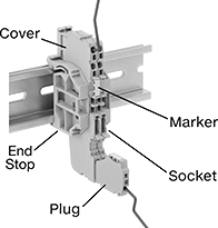
Quick-Connect Plug-and-Socket Modular DIN-Rail Mount Terminal Blocks
 |
Terminal Blocks | Covers | End Stops | Adjacent Jumpers | ||||||||||||||
|---|---|---|---|---|---|---|---|---|---|---|---|---|---|---|---|---|---|
No. of Circuits | No. of Terminals per Circuit | For Wire Ga. | Wd., mm | Ht., mm | Color | For DIN Rail Trade Size | Each | Each | Each | Insulation | Each | ||||||
300V AC/300V DC—10 amp per Circuit | |||||||||||||||||
| 1 | 1 | 24 to 16 | 3.5 | 48.5 | Blue | 3 | 4053N12 | 00000 | 4053N401 | 00000 | 9473T144 | 00000 | Insulated | 4280N401 | 00000 | ||
| 1 | 1 | 24 to 16 | 3.5 | 48.5 | Gray | 3 | 4053N11 | 0000 | 4053N401 | 0000 | 9473T144 | 0000 | Insulated | 4280N401 | 0000 | ||
| 1 | 1 | 24 to 16 | 3.5 | 58.2 | Blue | 3 | 4053N15 | 0000 | 4053N402 | 0000 | 9473T144 | 0000 | Insulated | 4280N401 | 0000 | ||
| 1 | 1 | 24 to 16 | 3.5 | 58.2 | Gray | 3 | 4053N14 | 0000 | 4053N402 | 0000 | 9473T144 | 0000 | Insulated | 4280N401 | 0000 | ||
| 1 | 1 | 24 to 16 | 3.5 | 85.25 | Blue | 3 | 4053N18 | 0000 | 4053N403 | 0000 | 9473T144 | 0000 | Insulated | 4280N401 | 0000 | ||
| 1 | 1 | 24 to 16 | 3.5 | 85.25 | Gray | 3 | 4053N17 | 0000 | 4053N403 | 0000 | 9473T144 | 0000 | Insulated | 4280N401 | 0000 | ||
Blank |
For Terminal Block Wd., mm | Markers per Card | Color | Each | |||
|---|---|---|---|---|---|---|
Blank | ||||||
| 3.5 | 100 | White | 4053N501 | 00000 | ||
Terminal Blocks | Covers | End Stops | Adjacent Jumpers | ||||||||||||||
|---|---|---|---|---|---|---|---|---|---|---|---|---|---|---|---|---|---|
No. of Circuits | No. of Terminals per Circuit | For Wire Ga. | Wd., mm | Ht., mm | Color | For DIN Rail Trade Size | Each | Each | Each | Insulation | Each | ||||||
| 1 | 1 | 24 to 16 | 3.5 | 50.8 | Green/Yellow | 3 | 4053N13 | 00000 | 4053N401 | 00000 | 9473T144 | 00000 | Insulated | 4280N401 | 00000 | ||
| 1 | 1 | 24 to 16 | 3.5 | 61.8 | Green/Yellow | 3 | 4053N16 | 0000 | 4053N402 | 0000 | 9473T144 | 0000 | Insulated | 4280N401 | 0000 | ||
| 1 | 1 | 24 to 16 | 3.5 | 85.25 | Green/Yellow | 3 | 4053N19 | 0000 | 4053N403 | 0000 | 9473T144 | 0000 | Insulated | 4280N401 | 0000 | ||
Blank |
For Terminal Block Wd., mm | Markers per Card | Color | Each | |||
|---|---|---|---|---|---|---|
Blank | ||||||
| 3.5 | 100 | White | 4053N501 | 00000 | ||
