


Filter by
Body Material
Expansion Plug Type

Maximum Air Back Pressure
Sealing Location
Maximum Pressure
Fitting Material
Overall Height
DFARS Specialty Metals
Height
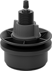
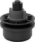
Compact Pressure-Relief Valves
Steel Body—For Air
 |
Inlet | Each | |||||||||
|---|---|---|---|---|---|---|---|---|---|---|
Pipe Size | Location | Max. Pressure | Relief Port Location | Overall Ht. | Set Pressure | 1-9 | 10-Up | |||
NPTF Male Inlet and Relief Vent | ||||||||||
| 1/8 | Bottom | 1 psi | Top | 1/2" | 0.3 psi | 1093K11 | 00000 | 00000 | ||
| 1/4 | Bottom | Not Rated | Top | 1 1/8" | 1 psi | 1093K21 | 00000 | 00000 | ||
| 1/4 | Bottom | Not Rated | Top | 1 1/8" | 7.5 psi | 1093K22 | 00000 | 00000 | ||
| 1/4 | Bottom | Not Rated | Top | 1 1/8" | 15 psi | 1093K23 | 00000 | 00000 | ||
| 3/8 | Bottom | Not Rated | Top | 1 3/16" | 1 psi | 1093K31 | 00000 | 00000 | ||
| 3/8 | Bottom | Not Rated | Top | 1 3/16" | 7.5 psi | 1093K32 | 00000 | 00000 | ||
| 1/2 | Bottom | Not Rated | Top | 1 3/8" | 1 psi | 1093K41 | 00000 | 00000 | ||
| 1/2 | Bottom | Not Rated | Top | 1 3/8" | 7.5 psi | 1093K42 | 00000 | 00000 | ||
Steel Body—For Grease and Oil
 |
Inlet | Each | |||||||||
|---|---|---|---|---|---|---|---|---|---|---|
Pipe Size | Location | Max. Pressure, psi | Relief Port Location | Overall Ht. | Set Pressure | 1-9 | 10-Up | |||
NPTF Male Inlet and Relief Vent | ||||||||||
| 1/8 | Bottom | 5 | Top | 1/2" | 1 psi | 1093K1 | 00000 | 00000 | ||
| 1/8 | Bottom | 15 | Top | 1/2" | 7.5 psi | 1093K2 | 0000 | 0000 | ||
| 1/8 | Bottom | 25 | Top | 1/2" | 15 psi | 1093K3 | 0000 | 0000 | ||
| 1/8 | Bottom | 80 | Top | 17/32" | 45 psi | 1093K4 | 0000 | 0000 | ||
| 1/8 | Bottom | 140 | Top | 9/16" | 80 psi | 1093K53 | 0000 | 0000 | ||
| 1/8 | Bottom | 200 | Top | 1/2" | 100 psi | 1093K64 | 0000 | 0000 | ||
BSPT Male Inlet and Relief Vent | ||||||||||
| 1/8 | Bottom | 1 | Top | 1/2" | 0.3 psi | 1093K61 | 0000 | 0000 | ||
| 1/8 | Bottom | 5 | Top | 1/2" | 1 psi | 1093K62 | 0000 | 0000 | ||
| 1/8 | Bottom | 80 | Top | 1/2" | 45 psi | 1093K63 | 0000 | 0000 | ||
Breather Vents
 |  |
Style D | Style E |
Protect against excess vacuum and pressure in cylinders, gear boxes, enclosures, manifolds, and tanks. You can also use these breather vents to block debris from entering equipment.
Splash Guard—Breather vents with splash guard are good for containers that are often filled and drained; they have a guard that prevents oil from splashing out of the vent hole.
Style | Pipe Size | Max. Flow Rate @ Pressure | Max. Pressure | Max. Temp., ° F | Ht. | For Use With | Removes Particle Size Down To, μm | Features | Each | |||
|---|---|---|---|---|---|---|---|---|---|---|---|---|
NPT Male | ||||||||||||
Zinc-Plated Steel Body and Fitting | ||||||||||||
| D | 1/8 | Not Rated | Not Rated | 225 | 1" | Air, Inert Gas, Oil, Water | 40 | — | 2257K11 | 000000 | ||
| D | 1/4 | Not Rated | Not Rated | 225 | 1" | Air, Inert Gas, Oil, Water | 40 | — | 2257K12 | 00000 | ||
| D | 3/8 | Not Rated | Not Rated | 225 | 1 1/16" | Air, Inert Gas, Oil, Water | 40 | — | 2257K13 | 00000 | ||
| D | 1/2 | Not Rated | Not Rated | 225 | 1 3/16" | Air, Inert Gas, Oil, Water | 40 | — | 2257K14 | 00000 | ||
| D | 3/4 | Not Rated | Not Rated | 225 | 1 1/4" | Air, Inert Gas, Oil, Water | 40 | — | 2257K15 | 00000 | ||
| E | 1/8 | Not Rated | Not Rated | 225 | 1 3/16" | Air, Inert Gas, Oil, Water | 40 | Splash Guard | 2257K31 | 00000 | ||
| E | 1/4 | Not Rated | Not Rated | 225 | 1 3/16" | Air, Inert Gas, Oil, Water | 40 | Splash Guard | 2257K32 | 00000 | ||
| E | 3/8 | Not Rated | Not Rated | 225 | 1 1/4" | Air, Inert Gas, Oil, Water | 40 | Splash Guard | 2257K33 | 00000 | ||
| E | 1/2 | Not Rated | Not Rated | 225 | 1 5/16" | Air, Inert Gas, Oil, Water | 40 | Splash Guard | 2257K34 | 00000 | ||
| E | 3/4 | Not Rated | Not Rated | 225 | 1 3/8" | Air, Inert Gas, Oil, Water | 40 | Splash Guard | 2257K35 | 00000 | ||
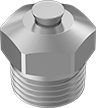
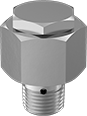
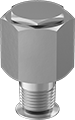
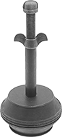
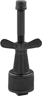
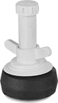
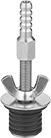
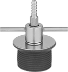
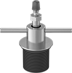
Expansion Plugs with Bypass
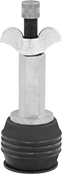 |  |  |
Style A | Style B | Style C |
 |  |  |
Style D | Style E | Style F |
 |  | |
Style G | Style H | Style J |
 |  | |
Style K | Style L |
Use the bypass tube on these plugs to add air, water, and other fluid to your pipeline or to relieve pressure while testing. The seal expands to temporarily close off pipe openings.
Style A—For Style A, twist the wing nut to expand the seal. They have an NPS threaded bypass for routing moderately pressurized fluids.
Style B—For Style B, twist the wing nut to expand the seal. They have an NPS threaded bypass for routing moderately pressurized fluids.
Style C—For Style C, twist the wing nut to expand the seal. They have an NPT threaded bypass for making leak-tight connections.
Style D—For Style D, twist the wing nut to expand the seal. They have an NPT threaded bypass for making leak-tight connections.
Style E—For Style E, twist the wing nut to expand the seal. They have a barbed bypass for quick connections to tubing.
Style F—For Style F, twist the easy-grip T-handle to expand the seal. They have a barbed bypass for quick connections to tubing.
Style G—For Style G, twist the easy-grip T-handle to expand the seal. They have a Schrader valve bypass. An internal spring holds the valve shut until you depress the pin, giving you control over air flow.
Style H—For Style H, twist the wing nut to expand the seal. They have a bypass with BSPP threads, also known as G threads, for making leak-tight connections.
Style J—For Style J, twist the wing nut to expand the seal. They have a Schrader valve bypass. An internal spring holds the valve shut until you depress the pin, giving you control over air flow.
Style K—For Style K, twist the wing nut to expand the seal. They have a Schrader valve bypass. An internal spring holds the valve shut until you depress the pin, giving you control over air flow.
Style L—For Style L, twist the wing nut to expand the seal. They have a GHT bypass that connects to standard garden hoses. Ideal for pipe cleanout, they allow for easy, controlled drainage.
Maximum Air Back Pressure—Maximum air back pressure is the amount of pressure a plug can withstand without moving.
Maximum Water Back Pressure—Maximum water back pressure refers to the pressure resulting from the height of the water above the plug.
For Pipe | Max. Back Pressure | Material | Bypass | |||||||||||||||
|---|---|---|---|---|---|---|---|---|---|---|---|---|---|---|---|---|---|---|
Size | ID | Air | Water, ft. of head | Overall Ht. | Temp. Range, ° F | Seal | Bypass Cap | Hose Size | Pipe Size | Thread Type | Thread Size | Gender | For Tube ID | Connection | Each | |||
Style A | ||||||||||||||||||
Aluminum Stem | ||||||||||||||||||
| 1 1/2 | 1.53" to 2.25" | 125 psi | 288 | 8 1/4" | -20 to 170 | Natural Rubber | Metal | — | 3/8 | NPS | — | Male | — | — | 2602K21 | 000000 | ||
| 2 | 1.79" to 2.38" | 125 psi | 288 | 8 1/4" | -20 to 170 | Natural Rubber | Metal | — | 3/8 | NPS | — | Male | — | — | 2602K22 | 00000 | ||
| 3 | 2.77" to 3.25" | 125 psi | 288 | 8 1/4" | -20 to 170 | Natural Rubber | Metal | — | 3/8 | NPS | — | Male | — | — | 2602K24 | 00000 | ||
| 4 | 3.85" to 4.25" | 35 psi | 81 | 8 1/4" | -20 to 170 | Natural Rubber | Metal | — | 1/2 | NPS | — | Male | — | — | 2602K25 | 00000 | ||
Style B | ||||||||||||||||||
Steel Stem | ||||||||||||||||||
| 6 | 5.80" to 6.50" | 20 psi | 46 | 12" | 35 to 210 | Natural Rubber | Metal | — | 1/2 | NPS | — | Male | — | — | 2602K16 | 000000 | ||
Style C | ||||||||||||||||||
Iron Stem | ||||||||||||||||||
| 1/2 | 0.47" to 0.50" | Not Rated | 46 | 4 1/4" | 30 to 150 | Natural Rubber | Metal | — | 1/16 | NPT | — | Male | — | — | 2644K15 | 00000 | ||
| 3/4 | 0.72" to 0.75" | Not Rated | 46 | 5 1/8" | 30 to 150 | Natural Rubber | Metal | — | 1/8 | NPT | — | Male | — | — | 2644K16 | 00000 | ||
| 1 | 0.97" to 1.00" | Not Rated | 46 | 5" | 30 to 150 | Natural Rubber | Metal | — | 1/4 | NPT | — | Male | — | — | 2644K18 | 00000 | ||
| 2 | 1.75" to 2.00" | Not Rated | 34 | 10 3/8" | 30 to 150 | Natural Rubber | Metal | — | 1/2 | NPT | — | Male | — | — | 2644K21 | 00000 | ||
| 3 | 2.75" to 3.00" | Not Rated | 34 | 10 1/2" | 30 to 150 | Natural Rubber | Metal | — | 1/2 | NPT | — | Male | — | — | 2644K22 | 00000 | ||
| 4 | 3.63" to 4.00" | Not Rated | 23 | 10 1/8" | 30 to 150 | Natural Rubber | Metal | — | 1/2 | NPT | — | Male | — | — | 2644K23 | 00000 | ||
| 5 | 4.50" to 5.00" | Not Rated | 23 | 12 5/8" | 30 to 150 | Natural Rubber | Metal | — | 1/2 | NPT | — | Male | — | — | 2644K24 | 00000 | ||
| 6 | 5.50" to 6.00" | Not Rated | 23 | 12 1/2" | 30 to 150 | Natural Rubber | Metal | — | 1/2 | NPT | — | Male | — | — | 2644K25 | 00000 | ||
| 8 | 7.50" to 8.00" | Not Rated | 4 | 14 3/4" | 30 to 150 | Natural Rubber | Metal | — | 1/2 | NPT | — | Male | — | — | 2644K26 | 00000 | ||
| 10 | 9.50" to 10.00" | Not Rated | 4 | 14 7/8" | 30 to 150 | Natural Rubber | Metal | — | 1/2 | NPT | — | Male | — | — | 2644K31 | 000000 | ||
| 12 | 11.50" to 12.00" | Not Rated | 4 | 14 5/8" | 30 to 150 | Natural Rubber | Metal | — | 1 | NPT | — | Male | — | — | 2644K32 | 000000 | ||
Style D | ||||||||||||||||||
Plastic Stem | ||||||||||||||||||
| 1 1/2 | 1.42" to 1.93" | 50 psi | 115 | 4 1/2" | -40 to 180 | Natural Rubber | Plastic | — | 1/2 | NPT | — | Male | — | — | 2566K35 | 00000 | ||
| 2 | 1.93" to 2.36" | 40 psi | 92 | 4 1/2" | -40 to 180 | Natural Rubber | Plastic | — | 1/2 | NPT | — | Male | — | — | 2566K36 | 00000 | ||
| 2 1/2 | 2.40" to 2.76" | 30 psi | 69 | 4 1/2" | -40 to 180 | Natural Rubber | Plastic | — | 1/2 | NPT | — | Male | — | — | 2566K37 | 00000 | ||
| 3 | 2.87" to 3.31" | 15 psi | 34 | 4 1/2" | -40 to 180 | Natural Rubber | Plastic | — | 1/2 | NPT | — | Male | — | — | 2566K38 | 00000 | ||
| 4 | 3.54" to 4.25" | 15 psi | 34 | 4 1/2" | -40 to 180 | Natural Rubber | Plastic | — | 1/2 | NPT | — | Male | — | — | 2566K39 | 00000 | ||
| 5 | 4.72" to 5.37" | 12 psi | 27 | 4 1/2" | -40 to 180 | Natural Rubber | Plastic | — | 1/2 | NPT | — | Male | — | — | 2566K41 | 00000 | ||
| 6 | 5.50" to 6.29" | 10 psi | 23 | 4 1/2" | -40 to 180 | Natural Rubber | Plastic | — | 1/2 | NPT | — | Male | — | — | 2566K42 | 00000 | ||
Style E | ||||||||||||||||||
Stainless Steel Stem | ||||||||||||||||||
| 1/2 | 0.48" to 0.53" | 10 psi | 24 | 3 1/2" | -40 to 250 | Neoprene | — | — | — | — | — | — | 1/4" | Barbed | 2516K31 | 000000 | ||
| 5/8 | 0.60" to 0.67" | 10 psi | 24 | 3 1/2" | -40 to 250 | Neoprene | — | — | — | — | — | — | 1/4" | Barbed | 2516K32 | 000000 | ||
| 3/4 | 0.72" to 0.79" | 10 psi | 24 | 3 1/2" | -40 to 250 | Neoprene | — | — | — | — | — | — | 1/4" | Barbed | 2516K33 | 000000 | ||
| 7/8 | 0.81" to 0.89" | 10 psi | 24 | 3 1/2" | -40 to 250 | Neoprene | — | — | — | — | — | — | 1/4" | Barbed | 2516K34 | 000000 | ||
Style F | ||||||||||||||||||
Stainless Steel Stem | ||||||||||||||||||
| 1 | 0.94" to 1.03" | 10 psi | 24 | 4" | -40 to 250 | Neoprene | — | — | — | — | — | — | 1/4" | Barbed | 2516K35 | 000000 | ||
| 1 1/8 | 1.06" to 1.17" | 5 psi | 12 | 4" | -40 to 250 | Neoprene | — | — | — | — | — | — | 1/4" | Barbed | 2516K36 | 000000 | ||
| 1 1/4 | 1.21" to 1.33" | 5 psi | 12 | 4" | -40 to 250 | Neoprene | — | — | — | — | — | — | 1/4" | Barbed | 2516K37 | 000000 | ||
| 1 1/2 | 1.44" to 1.58" | 5 psi | 12 | 4" | -40 to 250 | Neoprene | — | — | — | — | — | — | 1/4" | Barbed | 2516K39 | 000000 | ||
| 1 3/4 | 1.70" to 1.87" | 5 psi | 12 | 4" | -40 to 250 | Neoprene | — | — | — | — | — | — | 1/4" | Barbed | 2516K42 | 000000 | ||
| 2 | 1.92" to 2.14" | 5 psi | 12 | 4" | -40 to 250 | Neoprene | — | — | — | — | — | — | 1/4" | Barbed | 2516K44 | 000000 | ||
| — | 1.32" to 1.45" | 5 psi | 12 | 4" | -40 to 250 | Neoprene | — | — | — | — | — | — | 1/4" | Barbed | 2516K38 | 000000 | ||
Style G | ||||||||||||||||||
Zinc-Plated Steel Stem | ||||||||||||||||||
| 1 | 0.94" to 1.03" | 10 psi | 23 | 3 3/4" | -40 to 210 | Neoprene | Plastic | — | — | Schrader | 0.305"-32 | — | — | — | 5055N113 | 000000 | ||
| 1 1/2 | 1.44" to 1.58" | 10 psi | 23 | 4" | -40 to 210 | Neoprene | Plastic | — | — | Schrader | 0.305"-32 | — | — | — | 5055N117 | 000000 | ||
| 2 1/2 | 2.44" to 2.71" | 5 psi | 12 | 4 15/16" | -40 to 210 | Neoprene | Plastic | — | — | Schrader | 0.305"-32 | — | — | — | 5055N124 | 000000 | ||
Style H | ||||||||||||||||||
Plastic Stem | ||||||||||||||||||
| 1/2 | 0.49" to 0.60" | 100 psi | 231 | 2 15/16" | -40 to 180 | Natural Rubber | Plastic | — | 1/8 | BSPP | — | Male | — | — | 2566K11 | 00000 | ||
| 3/4 | 0.74" to 0.90" | 100 psi | 231 | 2 15/16" | -40 to 180 | Natural Rubber | Plastic | — | 1/8 | BSPP | — | Male | — | — | 2566K12 | 00000 | ||
| 1 | 0.98" to 1.20" | 100 psi | 231 | 2 15/16" | -40 to 180 | Natural Rubber | Plastic | — | 1/8 | BSPP | — | Male | — | — | 2566K13 | 00000 | ||
| 1 1/4 | 1.23" to 1.45" | 50 psi | 115 | 2 15/16" | -40 to 180 | Natural Rubber | Plastic | — | 1/8 | BSPP | — | Male | — | — | 2566K14 | 00000 | ||
Style J | ||||||||||||||||||
Zinc-Plated Steel Stem | ||||||||||||||||||
| 3/4 | 0.72" to 0.79" | 10 psi | 23 | 3 7/16" | -40 to 210 | Neoprene | Plastic | — | — | Schrader | 0.305"-32 | — | — | — | 5055N111 | 000000 | ||
| 7/8 | 0.81" to 0.89" | 10 psi | 23 | 3 5/8" | -40 to 210 | Neoprene | Plastic | — | — | Schrader | 0.305"-32 | — | — | — | 5055N112 | 000000 | ||
Style K | ||||||||||||||||||
Plastic Stem | ||||||||||||||||||
| 1 1/2 | 1.50" to 1.71" | 40 psi | 92 | 3 3/4" | — | PVC | Plastic | — | — | Schrader | 0.305"-32 | — | — | — | 2566K61 | 00000 | ||
| 2 | 1.86" to 2.06" | 30 psi | 69 | 3 3/4" | — | PVC | Plastic | — | — | Schrader | 0.305"-32 | — | — | — | 2566K62 | 00000 | ||
| 3 | 2.84" to 3.09" | 20 psi | 46 | 3 3/4" | — | PVC | Plastic | — | — | Schrader | 0.305"-32 | — | — | — | 2566K63 | 00000 | ||
| 4 | 3.89" to 4.15" | 10 psi | 23 | 3 3/4" | — | PVC | Plastic | — | — | Schrader | 0.305"-32 | — | — | — | 2566K64 | 00000 | ||
Style L | ||||||||||||||||||
Plastic Stem | ||||||||||||||||||
| 1 1/2 | 1.50" to 1.71" | 40 psi | 92 | 3 3/4" | — | PVC | Plastic | 3/4 | — | GHT | — | Male | — | — | 2566K51 | 0000 | ||
| 2 | 1.86" to 2.06" | 30 psi | 69 | 3 3/4" | — | PVC | Plastic | 3/4 | — | GHT | — | Male | — | — | 2566K52 | 0000 | ||
| 3 | 2.84" to 3.09" | 20 psi | 46 | 3 3/4" | — | PVC | Plastic | 3/4 | — | GHT | — | Male | — | — | 2566K53 | 0000 | ||
| 4 | 3.89" to 4.15" | 10 psi | 23 | 3 3/4" | — | PVC | Plastic | 3/4 | — | GHT | — | Male | — | — | 2566K54 | 0000 | ||
Self-Draining Breather Vents
Threaded NPT Male
 |
316 Stainless Steel Body and Fitting—316 stainless steel breather vents have excellent corrosion resistance.
Brass Body and Fitting—Brass breather vents have good corrosion resistance.
Pipe Size | Max. Flow Rate @ Pressure | Max. Pressure | Max. Temp., ° F | Ht. | Dia. | For Use With | Environment | Hazardous Location Protection Type | Enclosure Rating | Hazardous Location Rating | O-Ring Material | Certification | Features | Each | |||
|---|---|---|---|---|---|---|---|---|---|---|---|---|---|---|---|---|---|
316 Stainless Steel Body and Fitting | |||||||||||||||||
| 1/4 | Not Rated | Not Rated | 320 | 1 1/16" | 11/16" | Air | Corrosive, Dusty, Outdoor, Washdown, Wet | — | IP66, NEMA 4X | — | Silicone Rubber | — | Drain | 8602T31 | 000000 | ||
| 1/2 | Not Rated | Not Rated | 320 | 1 1/8" | 1" | Air | Corrosive, Dusty, Hazardous, Outdoor, Washdown, Wet | Increased Safety, Protection by Enclosure | IP66, NEMA 4X | ATEX I M2 Ex E I Mb; ATEX II 2 GD Ex E IIC Gb Ex Tb IIIC Db; IEC Zone 1 Groups IIC, IIB, IIA; IEC Zone 21 Groups IIIC, IIIB, IIIA; IECEx Ex E I/IIC Mb/Gb; IECEx Ex IIIC Tb Db | Silicone Rubber | CE Marked | Drain | 8602T32 | 00000 | ||
Brass Body and Fitting | |||||||||||||||||
| 1/4 | Not Rated | Not Rated | 320 | 1 1/16" | 11/16" | Air | Corrosive, Dusty, Outdoor, Washdown, Wet | — | IP66, NEMA 4X | — | Silicone Rubber | — | Drain | 8602T11 | 00000 | ||
| 1/2 | Not Rated | Not Rated | 320 | 1 1/8" | 1" | Air | Corrosive, Dusty, Hazardous, Outdoor, Washdown, Wet | Increased Safety, Protection by Enclosure | IP66, NEMA 4X | ATEX I M2 Ex E I Mb; ATEX II 2 GD Ex E IIC Gb Ex Tb IIIC Db; IEC Zone 1 Groups IIC, IIB, IIA; IEC Zone 21 Groups IIIC, IIIB, IIIA; IECEx Ex E I/IIC Mb/Gb; IECEx Ex IIIC Tb Db | Silicone Rubber | CE Marked | Drain | 8602T12 | 00000 | ||
Air-Inflatable Plugs with Bypass
With Zinc-Plated Steel Chain/Ring
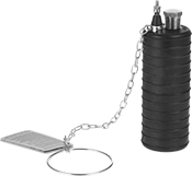 |
Maximum Air Back Pressure—Maximum air back pressure is the amount of pressure a plug can withstand without moving.
Maximum Water Back Pressure—Maximum water back pressure refers to the pressure resulting from the height of the water above the plug.
For Pipe | Deflated | Max. Back Pressure | Bypass | ||||||||||||
|---|---|---|---|---|---|---|---|---|---|---|---|---|---|---|---|
Size | ID | Dia. | Ht. | Chain Lg., ft. | Air, psi | Water, ft. of head | Req. Inflation Pressure, psi | Pipe Size | Thread Type | Gender | Temp. Range, ° F | Seal Material | Each | ||
| 1 1/2 | 1.49" to 1.88" | 1 3/8" | 3 13/16" | 1 | 22 | 50 | 40 | 1/4 | NPT | Male | -20 to 125 | Natural Rubber | 2580K23 | 0000000 | |
| 2 | 1.88" to 2.25" | 1 3/4" | 6" | 1 | 22 | 50 | 40 | 1/8 | NPT | Female | -20 to 125 | Natural Rubber | 2580K25 | 000000 | |
| 3 | 2.62" to 3.25" | 2 1/2" | 8" | 1 | 22 | 50 | 40 | 1/2 | NPT | Female | -20 to 125 | Natural Rubber | 2580K27 | 000000 | |
With Zinc-Plated Steel Eyebolt
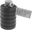 |
Maximum Air Back Pressure—Maximum air back pressure is the amount of pressure a plug can withstand without moving.
Maximum Water Back Pressure—Maximum water back pressure refers to the pressure resulting from the height of the water above the plug.
For Pipe | Deflated | Max. Back Pressure | Bypass | |||||||||||
|---|---|---|---|---|---|---|---|---|---|---|---|---|---|---|
Size | ID | Dia. | Ht. | Air, psi | Water, ft. of head | Req. Inflation Pressure, psi | Pipe Size | Thread Type | Gender | Temp. Range, ° F | Seal Material | Each | ||
| 4 | 3.25" to 4.25" | 3 1/8" | 8" | 22 | 50 | 40 | 3/4 | NPT | Female | -20 to 125 | Natural Rubber | 2580K21 | 0000000 | |
| 6 | 4.50" to 6.25" | 4 1/2" | 7" | 13 | 30 | 35 | 1 1/2 | NPT | Female | -20 to 125 | Natural Rubber | 2580K11 | 000000 | |
| 8 | 7.00" to 8.25" | 6 3/4" | 10" | 13 | 30 | 35 | 3 | NPT | Female | -20 to 125 | Natural Rubber | 2580K12 | 000000 | |
| 10 | 9.00" to 10.25" | 8 3/4" | 11 3/4" | 13 | 30 | 35 | 3 | NPT | Female | -20 to 125 | Natural Rubber | 2580K13 | 000000 | |
| 12 | 10.50" to 12.25" | 10 1/4" | 13 3/4" | 13 | 30 | 35 | 3 | NPT | Female | -20 to 125 | Natural Rubber | 2580K14 | 000000 | |
| 12 to 24 | 11.25" to 24.00" | 11" | 37" | 13 | 30 | 45 | 3 | NPT | Male | -20 to 125 | Natural Rubber | 2580K313 | 00000000 | |
| 16 | 14.00" to 16.00" | 13 3/4" | 19 3/4" | 13 | 30 | 35 | 3 | NPT | Female | -20 to 125 | Natural Rubber | 2580K29 | 000000 | |
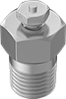
Pressure-Venting Grease Fittings
 |
Straight with Male Thread
Each | |||||||||||
|---|---|---|---|---|---|---|---|---|---|---|---|
Material | Overall Ht. | Thread Lg. | Shank Lg. | Hex Size | Max. Pressure | Check Valve Type | 1-9 | 10-Up | |||
1/8 PTF-SAE Thread | |||||||||||
| Zinc-Plated Steel | 41/64" | 9/32" | 9/32" | 7/16" | Not Rated | Ball | 4334N11 | 00000 | 00000 | ||
Long-Reach Hex-Nut Expansion Plugs with Bypass
Plug your pipe from the inside. Insert these expansion plugs deep into your pipe, and then tighten the nut on the stem. Use the bypass tube to add air, water, and fluid or relieve back pressure.
Maximum Air Back Pressure—Maximum air back pressure is the amount of pressure a plug can withstand without moving.
Maximum Water Back Pressure—Maximum water back pressure refers to the pressure resulting from the height of the water above the plug.
For Pipe | Max. Back Pressure | Bypass | |||||||||||
|---|---|---|---|---|---|---|---|---|---|---|---|---|---|
Size | ID | Air, psi | Water, ft. of head | Overall Ht. | Temp. Range, ° F | Seal Material | Pipe Size | Thread Type | Gender | Each | |||
Zinc-Plated Steel Stem | |||||||||||||
| 1/2 | 0.62" to 0.64" | 250 | 576 | 4 3/8" | -20 to 225 | Neoprene | 1/8 | NPT | Male | 2564K31 | 0000000 | ||
| 3/4 | 0.81" to 0.82" | 175 | 403 | 4 3/8" | -20 to 225 | Neoprene | 1/8 | NPT | Male | 2564K32 | 000000 | ||
| 1 | 1.03" to 1.05" | 175 | 403 | 6 3/8" | -20 to 225 | Neoprene | 1/8 | NPT | Male | 2564K33 | 000000 | ||
| 1 1/4 | 1.37" to 1.39" | 175 | 403 | 6 3/8" | -20 to 225 | Neoprene | 1/8 | NPT | Male | 2564K34 | 000000 | ||
| 1 1/2 | 1.58" to 1.61" | 75 | 173 | 6 3/8" | -20 to 225 | Neoprene | 1/8 | NPT | Male | 2564K35 | 000000 | ||
| 2 | 2.03" to 2.07" | 75 | 173 | 6 3/8" | -20 to 225 | Neoprene | 1/8 | NPT | Male | 2564K36 | 000000 | ||
| 3 | 3.03" to 3.13" | 50 | 115 | 4 3/8" | -20 to 225 | Neoprene | 1/4 | NPT | Male | 2564K48 | 000000 | ||
