


Filter by
System of Measurement
Material
Fitting Connection
Thread Type
For Use With
Body Material
Screen Material
Screen Construction

Maximum Pressure
Removes Particle Size Down To
Screen Finished Material
Maximum Temperature

Height
Fitting Material
DFARS Specialty Metals
Export Control Classification Number (ECCN)
REACH
Environment
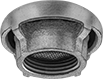
Weather Resistant Breather Vents
 |
Threaded NPT Female, Style B |
Shield outdoor pipe and tank openings from the environment. Also known as vent caps, these breather vents have screens to allow air flow while blocking debris. Use them to prevent excess vacuum and pressure in your equipment.
Threaded NPT Female
|
Style B |
Screen | |||||||||||||||
|---|---|---|---|---|---|---|---|---|---|---|---|---|---|---|---|
Style | Pipe Size | Max. Flow Rate @ Pressure | Max. Pressure | Max. Temp. | Ht. | Dia. | For Use With | Material | Construction | Mesh Size | Removes Particle Size Down To, μm | Each | |||
Zinc-Plated Iron Body and Fitting | |||||||||||||||
| B | 3/4 | Not Rated | Not Rated | Not Rated | 1 3/16" | 1 13/16" | Air | 304 Stainless Steel | Wire Mesh | 30 × 30 | 880 | 36635K41 | 000000 | ||
| B | 1 | Not Rated | Not Rated | Not Rated | 1 5/16" | 2 1/4" | Air | 304 Stainless Steel | Wire Mesh | 30 × 30 | 880 | 36635K42 | 00000 | ||
| B | 1 1/4 | Not Rated | Not Rated | Not Rated | 1 3/8" | 2 3/4" | Air | 304 Stainless Steel | Wire Mesh | 30 × 30 | 880 | 36635K43 | 00000 | ||
| B | 1 1/2 | Not Rated | Not Rated | Not Rated | 1 1/2" | 3 1/8" | Air | 304 Stainless Steel | Wire Mesh | 30 × 30 | 880 | 36635K44 | 00000 | ||
| B | 2 | Not Rated | Not Rated | Not Rated | 1 11/16" | 3 7/8" | Air | 304 Stainless Steel | Wire Mesh | 30 × 30 | 880 | 36635K45 | 00000 | ||
| B | 3 | Not Rated | Not Rated | Not Rated | 2 1/2" | 5 1/2" | Air | 304 Stainless Steel | Wire Mesh | 30 × 30 | 880 | 36635K46 | 000000 | ||
| B | 4 | Not Rated | Not Rated | Not Rated | 2 1/2" | 6 1/2" | Air | 304 Stainless Steel | Wire Mesh | 20 × 20 | 864 | 36635K47 | 000000 | ||
Remote-Discharge Air-Release Valves for Water
 |
Inlet | Relief Port | |||||||||
|---|---|---|---|---|---|---|---|---|---|---|
Pipe Size | Location | Pipe Size | Location | Max. Pressure, psi | Temp. Range, ° F | Overall Ht. | Each | |||
NPT Female Inlet and Relief Pipe | ||||||||||
Ductile Iron Body—Vertical Mount | ||||||||||
| 3/8 | Bottom | 3/8 | Top | 150 | 32 to 150 | 5 3/4" | 48045K93 | 0000000 | ||
| 1/2 | Bottom | 3/8 | Top | 150 | 32 to 150 | 5 3/4" | 48045K94 | 000000 | ||
| 1/2 | Bottom | 1/2 | Top | 300 | 32 to 150 | 5 1/2" | 48045K71 | 000000 | ||
| 3/4 | Bottom | 3/8 | Top | 150 | 32 to 150 | 5 3/4" | 48045K95 | 000000 | ||
| 3/4 | Bottom | 1/2 | Top | 300 | 32 to 150 | 5 1/2" | 48045K72 | 000000 | ||
| 1 | Bottom | 3/8 | Top | 150 | 32 to 150 | 5 3/4" | 48045K96 | 000000 | ||
| 1 | Bottom | 1/2 | Top | 150 | 32 to 150 | 9" | 48045K81 | 000000 | ||
| 1 | Bottom | 1/2 | Top | 300 | 32 to 150 | 5 1/2" | 48045K73 | 000000 | ||
| 2 | Bottom | 1/2 | Top | 150 | 32 to 150 | 9" | 48045K87 | 000000 | ||
| 2 | Bottom | 1/2 | Top | 150 | 32 to 150 | 10 1/2" | 48045K83 | 000000 | ||
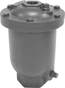
Air-Release Valves for Drinking Water
 |
Inlet | Relief Port | |||||||||
|---|---|---|---|---|---|---|---|---|---|---|
Pipe Size | Location | Pipe Size | Location | Max. Pressure, psi | Temp. Range, ° F | Overall Ht. | Each | |||
NPT Female Inlet and Relief Pipe | ||||||||||
Cast Iron Body—Vertical Mount | ||||||||||
| 1/2 | Bottom | 1/2 | Top | 300 | 33 to 225 | 7" | 4790T31 | 0000000 | ||
| 1 | Bottom | 1 | Top | 300 | 33 to 225 | 9 1/2" | 4790T32 | 000000 | ||
| 2 | Bottom | 2 | Top | 300 | 33 to 225 | 12" | 4790T33 | 000000 | ||
| 3 | Bottom | 3 | Top | 300 | 33 to 225 | 12" | 4790T34 | 00000000 | ||
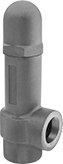
Hydraulic Pressure-Relief Valves
 |
Iron |
To set the pressure, unscrew the cap and turn the adjustment screw. Valves begin opening at the set pressure and fully open at about 10% over the set pressure. They begin closing as pressure drops and close when the system pressure is restored below the set pressure.
Iron Body—Iron valves absorb vibration to reduce noise and wear in the pipeline.
Inlet Connection | Relief Connection | Overall | ||||||||||
|---|---|---|---|---|---|---|---|---|---|---|---|---|
Pipe Size | Dash Size | Pipe Size | Dash Size | Lg. | Wd. | Ht. | Temp. Range, ° F | Choose a Set Pressure, psi | Each | |||
NPT Female Inlet and NPT Female Relief Port | ||||||||||||
Iron Body | ||||||||||||
| 3/8 | 06 | 3/8 | 06 | 2 1/16" | 1 3/8" | 5 3/8" | -20 to 400 | 3 to 10, 7 to 35, 30 to 100, 60 to 175, 150 to 350, 300 to 500 | 4704K32 | 0000000 | ||
| 1/2 | 08 | 1/2 | 08 | 2 5/16" | 1 7/16" | 6 3/16" | -20 to 400 | 3 to 10, 7 to 35, 30 to 100, 60 to 175, 150 to 350, 300 to 500 | 4704K11 | 000000 | ||
| 3/4 | 12 | 3/4 | 12 | 2 11/16" | 1 11/16" | 6 15/16" | -20 to 400 | 3 to 10, 7 to 35, 30 to 100, 60 to 175, 150 to 350, 300 to 500 | 4704K12 | 000000 | ||
| 1 | 16 | 1 | 16 | 3 5/16" | 2 1/16" | 8 1/4" | -20 to 400 | 3 to 10, 7 to 35, 30 to 100, 60 to 175, 150 to 350, 300 to 500 | 4704K13 | 000000 | ||
| 1 1/4 | 20 | 1 1/4 | 20 | 3 13/16" | 2 1/2" | 9 9/16" | -20 to 400 | 3 to 10, 7 to 35, 30 to 100, 60 to 175, 150 to 350, 300 to 500 | 4704K14 | 000000 | ||
| 1 1/2 | 24 | 1 1/2 | 24 | 4 1/8" | 2 7/8" | 11 1/16" | -20 to 400 | 3 to 10, 7 to 35, 30 to 100, 60 to 175, 150 to 350, 300 to 500 | 4704K25 | 000000 | ||
| 2 | 32 | 2 | 32 | 4 5/8" | 3 1/4" | 13" | -20 to 400 | 3 to 10, 7 to 35, 30 to 100, 60 to 175, 150 to 350, 250 to 600 | 4704K26 | 000000 | ||
High-Flow Iron Steam Traps
 | 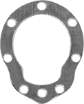 |
Replacement Pipe Gaskets |
Steam Traps | Replacement Pipe Gaskets | |||||||||||||||
|---|---|---|---|---|---|---|---|---|---|---|---|---|---|---|---|---|
Pipe Size | Thread Type | Gender | Pipeline Orientation | Fitting Connection | Max. Pressure, psi | Max. Temp., ° F | Condensate Cap., lb/hr | Lg. | Ht. | Each | Pkg. Qty. | Pkg. | ||||
Iron | ||||||||||||||||
| 1/2 | NPT | Female | Horizontal | Threaded | 15 | 450 | 1,040 | 5" | 6 3/8" | 4897K51 | 0000000 | 3 | 4897K11 | 0000000 | ||
| 1/2 | NPT | Female | Horizontal | Threaded | 30 | 450 | 1,000 | 5" | 6 3/8" | 4897K21 | 000000 | 3 | 4897K11 | 000000 | ||
| 1/2 | NPT | Female | Horizontal | Threaded | 75 | 450 | 965 | 5" | 6 3/8" | 4897K52 | 000000 | 3 | 4897K11 | 000000 | ||
| 1/2 | NPT | Female | Horizontal | Threaded | 125 | 450 | 920 | 5" | 6 3/8" | 4897K27 | 000000 | 3 | 4897K11 | 000000 | ||
| 1/2 | NPT | Female | Horizontal | Threaded | 250 | 450 | 720 | 5" | 6 3/8" | 4897K34 | 000000 | 3 | 4897K11 | 000000 | ||
| 3/4 | NPT | Female | Horizontal | Threaded | 15 | 450 | 1,040 | 5" | 6 3/8" | 4897K53 | 000000 | 3 | 4897K11 | 000000 | ||
| 3/4 | NPT | Female | Horizontal | Threaded | 15 | 450 | 3,220 | 6 5/8" | 7 5/8" | 4897K55 | 000000 | 3 | 4897K12 | 000000 | ||
| 3/4 | NPT | Female | Horizontal | Threaded | 30 | 450 | 1,000 | 5" | 6 3/8" | 4897K22 | 000000 | 3 | 4897K11 | 000000 | ||
| 3/4 | NPT | Female | Horizontal | Threaded | 30 | 450 | 3,220 | 6 5/8" | 7 5/8" | 4897K23 | 000000 | 3 | 4897K12 | 000000 | ||
| 3/4 | NPT | Female | Horizontal | Threaded | 75 | 450 | 965 | 5" | 6 3/8" | 4897K54 | 000000 | 3 | 4897K11 | 000000 | ||
| 3/4 | NPT | Female | Horizontal | Threaded | 75 | 450 | 2,550 | 6 5/8" | 7 5/8" | 4897K56 | 000000 | 3 | 4897K12 | 000000 | ||
| 3/4 | NPT | Female | Horizontal | Threaded | 125 | 450 | 920 | 5" | 6 3/8" | 4897K28 | 000000 | 3 | 4897K11 | 000000 | ||
| 3/4 | NPT | Female | Horizontal | Threaded | 125 | 450 | 2,240 | 6 5/8" | 7 5/8" | 4897K29 | 000000 | 3 | 4897K12 | 000000 | ||
| 3/4 | NPT | Female | Horizontal | Threaded | 250 | 450 | 720 | 5" | 6 3/8" | 4897K35 | 000000 | 3 | 4897K11 | 000000 | ||
| 3/4 | NPT | Female | Horizontal | Threaded | 250 | 450 | 2,300 | 6 5/8" | 7 5/8" | 4897K36 | 000000 | 3 | 4897K12 | 000000 | ||
| 1 | NPT | Female | Horizontal | Threaded | 15 | 450 | 3,900 | 8" | 9 1/4" | 4897K57 | 000000 | 3 | 4897K13 | 000000 | ||
| 1 | NPT | Female | Horizontal | Threaded | 30 | 450 | 4,120 | 8" | 9 1/4" | 4897K24 | 000000 | 3 | 4897K13 | 000000 | ||
| 1 | NPT | Female | Horizontal | Threaded | 75 | 450 | 3,960 | 8" | 9 1/4" | 4897K58 | 000000 | 3 | 4897K13 | 000000 | ||
| 1 | NPT | Female | Horizontal | Threaded | 125 | 450 | 4,100 | 8" | 9 1/4" | 4897K41 | 000000 | 3 | 4897K13 | 000000 | ||
| 1 | NPT | Female | Horizontal | Threaded | 250 | 450 | 3,630 | 8" | 9 1/4" | 4897K37 | 000000 | 3 | 4897K13 | 000000 | ||
| 1 1/4 | NPT | Female | Horizontal | Threaded | 125 | 450 | 8,540 | 9 3/8" | 13" | 4897K42 | 00000000 | 3 | 4897K14 | 000000 | ||
| 1 1/4 | NPT | Female | Horizontal | Threaded | 250 | 450 | 6,040 | 9 3/8" | 13" | 4897K38 | 00000000 | 3 | 4897K14 | 000000 | ||
| 2 | NPT | Female | Horizontal | Threaded | 30 | 450 | 18,500 | 11 1/4" | 17" | 4897K26 | 00000000 | 3 | 4897K15 | 000000 | ||
| 2 | NPT | Female | Horizontal | Threaded | 75 | 450 | 19,200 | 11 1/4" | 17" | 4897K63 | 00000000 | 3 | 4897K15 | 000000 | ||
| 2 | NPT | Female | Horizontal | Threaded | 125 | 450 | 20,000 | 11 1/4" | 17" | 4897K33 | 00000000 | 3 | 4897K15 | 000000 | ||
| 2 | NPT | Female | Horizontal | Threaded | 250 | 450 | 19,400 | 11 1/4" | 17" | 4897K39 | 00000000 | 3 | 4897K15 | 000000 | ||
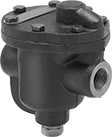
Energy-Saving Iron Steam Traps
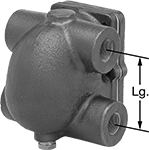 | 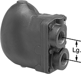 | 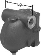 |
Style A | Style B | Style C |
Style | Pipe Size | Thread Type | Gender | Pipeline Orientation | Fitting Connection | Max. Pressure, psi | Max. Temp., ° F | Condensate Cap., lb/hr | Lg. | Ht. | Includes | Each | |||
|---|---|---|---|---|---|---|---|---|---|---|---|---|---|---|---|
Iron with Stainless Steel Float | |||||||||||||||
| A | 3/4 | NPT | Female | Horizontal | Threaded | 15 | 250 | 1,075 | 3 5/16" | 5 3/4" | Two Plugs for Unused Ports | 4913K51 | 0000000 | ||
| A | 3/4 | NPT | Female | Horizontal | Threaded | 30 | 270 | 1,370 | 3 5/16" | 5 3/4" | Two Plugs for Unused Ports | 4913K71 | 000000 | ||
| A | 3/4 | NPT | Female | Horizontal | Threaded | 75 | 320 | 1,450 | 3 5/16" | 5 3/4" | Two Plugs for Unused Ports | 4913K61 | 000000 | ||
| A | 3/4 | NPT | Female | Horizontal | Threaded | 125 | 350 | 1,190 | 3 5/16" | 5 3/4" | Two Plugs for Unused Ports | 4913K81 | 000000 | ||
| A | 1 | NPT | Female | Horizontal | Threaded | 15 | 250 | 1,075 | 3 5/16" | 5 3/4" | Two Plugs for Unused Ports | 4913K52 | 000000 | ||
| A | 1 | NPT | Female | Horizontal | Threaded | 30 | 270 | 1,370 | 3 5/16" | 5 3/4" | Two Plugs for Unused Ports | 4913K72 | 000000 | ||
| A | 1 | NPT | Female | Horizontal | Threaded | 75 | 320 | 1,450 | 3 5/16" | 5 3/4" | Two Plugs for Unused Ports | 4913K62 | 000000 | ||
| A | 1 | NPT | Female | Horizontal | Threaded | 125 | 350 | 1,190 | 3 5/16" | 5 3/4" | Two Plugs for Unused Ports | 4913K82 | 000000 | ||
| A | 1 1/4 | NPT | Female | Horizontal | Threaded | 15 | 250 | 2,340 | 3 5/16" | 5 3/4" | Two Plugs for Unused Ports | 4913K57 | 000000 | ||
| A | 1 1/4 | NPT | Female | Horizontal | Threaded | 30 | 270 | 2,000 | 3 5/16" | 5 3/4" | Two Plugs for Unused Ports | 4913K73 | 000000 | ||
| B | 1 1/4 | NPT | Female | Horizontal | Threaded | 75 | 320 | 5,400 | 3" | 8 3/8" | — | 4913K66 | 000000 | ||
| B | 1 1/4 | NPT | Female | Horizontal | Threaded | 125 | 350 | 4,500 | 3" | 8 3/8" | — | 4913K83 | 000000 | ||
| B | 1 1/2 | NPT | Female | Horizontal | Threaded | 15 | 250 | 7,600 | 3" | 8 3/8" | — | 4913K56 | 000000 | ||
| B | 1 1/2 | NPT | Female | Horizontal | Threaded | 30 | 270 | 7,000 | 3" | 8 3/8" | — | 4913K74 | 000000 | ||
| B | 1 1/2 | NPT | Female | Horizontal | Threaded | 75 | 320 | 5,400 | 3" | 8 3/8" | — | 4913K67 | 000000 | ||
| B | 1 1/2 | NPT | Female | Horizontal | Threaded | 125 | 350 | 4,500 | 3" | 8 3/8" | — | 4913K84 | 000000 | ||
| B | 2 | NPT | Female | Horizontal | Threaded | 15 | 250 | 10,900 | 4 15/16" | 9 1/8" | — | 4913K58 | 000000 | ||
| B | 2 | NPT | Female | Horizontal | Threaded | 30 | 270 | 10,000 | 4 15/16" | 9 1/8" | — | 4913K75 | 00000000 | ||
| B | 2 | NPT | Female | Horizontal | Threaded | 75 | 320 | 7,700 | 4 15/16" | 9 1/8" | — | 4913K68 | 00000000 | ||
| B | 2 | NPT | Female | Horizontal | Threaded | 125 | 350 | 6,600 | 4 15/16" | 9 1/8" | — | 4913K85 | 00000000 | ||
| C | 1/2 | NPT | Female | Horizontal | Threaded | 15 | 450 | 1,075 | 4 13/16" | 5 13/16" | — | 4913K111 | 000000 | ||
| C | 1/2 | NPT | Female | Horizontal | Threaded | 30 | 450 | 1,370 | 4 13/16" | 5 13/16" | — | 4913K112 | 000000 | ||
| C | 1/2 | NPT | Female | Horizontal | Threaded | 75 | 450 | 1,450 | 4 13/16" | 5 13/16" | — | 4913K113 | 000000 | ||
| C | 1/2 | NPT | Female | Horizontal | Threaded | 125 | 450 | 1,190 | 4 13/16" | 5 13/16" | — | 4913K114 | 000000 | ||
| C | 1/2 | NPT | Female | Horizontal | Threaded | 200 | 450 | 985 | 4 13/16" | 5 13/16" | — | 4913K115 | 000000 | ||
| C | 3/4 | NPT | Female | Horizontal | Threaded | 15 | 450 | 1,075 | 4 13/16" | 5 13/16" | — | 4913K211 | 000000 | ||
| C | 3/4 | NPT | Female | Horizontal | Threaded | 30 | 450 | 1,370 | 4 13/16" | 5 13/16" | — | 4913K212 | 000000 | ||
| C | 3/4 | NPT | Female | Horizontal | Threaded | 75 | 450 | 1,450 | 4 13/16" | 5 13/16" | — | 4913K213 | 000000 | ||
| C | 3/4 | NPT | Female | Horizontal | Threaded | 125 | 450 | 1,190 | 4 13/16" | 5 13/16" | — | 4913K214 | 000000 | ||
| C | 3/4 | NPT | Female | Horizontal | Threaded | 200 | 450 | 985 | 4 13/16" | 5 13/16" | — | 4913K215 | 000000 | ||
| C | 1 | NPT | Female | Horizontal | Threaded | 15 | 450 | 1,075 | 4 13/16" | 5 13/16" | — | 4913K311 | 000000 | ||
| C | 1 | NPT | Female | Horizontal | Threaded | 30 | 450 | 1,370 | 4 13/16" | 5 13/16" | — | 4913K312 | 000000 | ||
| C | 1 | NPT | Female | Horizontal | Threaded | 75 | 450 | 1,450 | 4 13/16" | 5 13/16" | — | 4913K313 | 000000 | ||
| C | 1 | NPT | Female | Horizontal | Threaded | 125 | 450 | 1,190 | 4 13/16" | 5 13/16" | — | 4913K314 | 000000 | ||
| C | 1 | NPT | Female | Horizontal | Threaded | 200 | 450 | 985 | 4 13/16" | 5 13/16" | — | 4913K315 | 000000 | ||
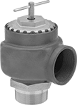
Large-Diameter Remote-Discharge ASME-Code Fast-Acting Pressure-Relief Valves for Air and Inert Gas
NPT Male Inlet and NPT Female Relief Port
 |
Inlet | Relief | |||||||||||||||
|---|---|---|---|---|---|---|---|---|---|---|---|---|---|---|---|---|
Pipe Size | Location | Max. Pressure, psi | Port Pipe Size | Port Location | Shape | Overall Ht. | For Use With | Temp. Range, ° F | Test Mechanism | Valve Type | Certification | Choose a Set Pressure, psi | Each | |||
Cast Iron Body—Bronze Seal | ||||||||||||||||
| 2 | Bottom | 60 | 2 | Side | 90° Elbow | 7" | Air, Inert Gas | -20 to 406 | T-Handle | Pop Safety | ASME BPVC.VIII | 16, 18, 20, 22, 24, 26, 28, 30, 32, 34, 36, 38, 40, 42, 44, 46, 48, 50, 52, 54, 56, 58, 60 | 8175K32 | 0000000 | ||
| 2 1/2 | Bottom | 60 | 2 1/2 | Side | 90° Elbow | 8" | Air, Inert Gas | -20 to 406 | T-Handle | Pop Safety | ASME BPVC.VIII | 16, 18, 20, 22, 24, 26, 28, 30, 32, 34, 36, 38, 40, 42, 44, 46, 48, 50, 52, 54, 56, 58, 60 | 8175K34 | 000000 | ||
| 3 | Bottom | 60 | 3 | Side | 90° Elbow | 9" | Air, Inert Gas | -20 to 406 | T-Handle | Pop Safety | ASME BPVC.VIII | 16, 18, 20, 22, 24, 26, 28, 30, 32, 34, 36, 38, 40, 42, 44, 46, 48, 50, 52, 54, 56, 58, 60 | 8175K36 | 00000000 | ||
Large-Diameter Remote-Discharge Fast-Acting Pressure-Relief Valves for Air and Inert Gas
NPT Male Inlet and NPT Female Relief Port
|
Inlet | Relief | ||||||||||||||
|---|---|---|---|---|---|---|---|---|---|---|---|---|---|---|---|
Pipe Size | Location | Max. Pressure, psi | Port Pipe Size | Port Location | Shape | Overall Ht. | For Use With | Temp. Range, ° F | Test Mechanism | Valve Type | Choose a Set Pressure, psi | Each | |||
Cast Iron Body—Bronze Seal | |||||||||||||||
| 2 | Bottom | 60 | 2 | Side | 90° Elbow | 7" | Air, Inert Gas | -20 to 406 | T-Handle | Pop Safety | 2, 4, 6, 8, 10, 12, 14 | 8175K31 | 0000000 | ||
| 2 1/2 | Bottom | 60 | 2 1/2 | Side | 90° Elbow | 8" | Air, Inert Gas | -20 to 406 | T-Handle | Pop Safety | 2, 4, 6, 8, 10, 12, 14 | 8175K33 | 000000 | ||
| 3 | Bottom | 60 | 3 | Side | 90° Elbow | 9" | Air, Inert Gas | -20 to 406 | T-Handle | Pop Safety | 2, 4, 6, 8, 10, 12, 14 | 8175K35 | 00000000 | ||
