


Filter by
Product Family
Outer Jacket Color
Length
Flexibility
Performance

Export Control Classification Number (ECCN)
DFARS Specialty Metals
Electrical Connection
Wire Strand Count
Wire Connection Method
Welding Cable
 |
 |
Per Ft. | ||||||||||||
|---|---|---|---|---|---|---|---|---|---|---|---|---|
AWG | Stranded Wire Class | Wire Strand Count | Outer Jacket Material | Temp., ° F | Flammability Rating | Choose an Outer Jacket Color | Choose a Length, ft. | 1-249 | 250-Up | |||
600V AC | ||||||||||||
Bend and Stay | ||||||||||||
| 8 | K | 182/30 | EPDM | -55 to 220 | UL 2556 VW-1 | Black, Red | 10, 20, 25, 30, 50, 100, 250 | 7940A86 | 00000 | 00000 | ||
| 6 | K | 260/30 | EPDM | -55 to 220 | UL 2556 VW-1 | Black, Red | 10, 20, 25, 30, 50, 100, 250 | 7940A91 | 0000 | 0000 | ||
| 4 | K | 364/30 | EPDM | -55 to 220 | UL 2556 VW-1 | Black, Red | 10, 20, 25, 30, 50, 100, 250 | 7940A92 | 0000 | 0000 | ||
| 2 | K | 624/30 | EPDM | -55 to 220 | UL 2556 VW-1 | Black, Red | 10, 20, 25, 30, 50, 100, 250 | 7940A93 | 0000 | 0000 | ||
| 1 | K | 767/30 | EPDM | -55 to 220 | UL 2556 VW-1 | Black, Red | 10, 20, 25, 30, 50, 100, 250 | 7940A94 | 0000 | 0000 | ||
| 1/0 | K | 975/30 | EPDM | -55 to 220 | UL 2556 VW-1 | Black, Red | 10, 20, 25, 30, 50, 100, 250 | 7940A95 | 0000 | 0000 | ||
| 2/0 | K | 1,196/30 | EPDM | -55 to 220 | UL 2556 VW-1 | Black, Red | 10, 20, 25, 30, 50, 100, 250 | 7940A96 | 00000 | 0000 | ||
| 3/0 | K | 1,547/30 | EPDM | -55 to 220 | UL 2556 VW-1 | Black, Red | 10, 20, 25, 30, 50, 100, 250 | 7940A97 | 00000 | 00000 | ||
| 4/0 | K | 1,950/30 | EPDM | -55 to 220 | UL 2556 VW-1 | Black, Red | 10, 20, 25, 30, 50, 100, 250 | 7940A98 | 00000 | 00000 | ||
600V AC/600V DC | ||||||||||||
Flexible | ||||||||||||
| 2 | M | 1,482/34 | EPDM | -55 to 220 | UL 2556 VW-1 | Orange | 10, 20, 25, 30, 50, 100, 250 | 7940A77 | 0000 | 0000 | ||
| 1 | M | 1,843/34 | EPDM | -55 to 220 | UL 2556 VW-1 | Orange | 10, 20, 25, 30, 50, 100, 250 | 7940A78 | 0000 | 0000 | ||
| 1/0 | M | 2,337/34 | EPDM | -55 to 220 | UL 2556 VW-1 | Orange | 10, 20, 25, 30, 50, 100, 250 | 7940A79 | 0000 | 0000 | ||
| 2/0 | M | 2,886/34 | EPDM | -55 to 220 | UL 2556 VW-1 | Orange | 10, 20, 25, 30, 50, 100, 250 | 7940A81 | 00000 | 0000 | ||
Welding Cable Connectors
Plugs
 |
Current, amp | Wire Connection | For Wire Ga. | For Cable OD | Housing Connection Method | OD | Lg. | Color | Temp. Range, ° F | Each | ||
|---|---|---|---|---|---|---|---|---|---|---|---|
| 250 | Screw Terminal | 4, 3, 2, 1, 1/0 | 0.2" to 0.5" | Push In | 1.3" | 5.9" | Black | -50 to 350 | 7841A14 | 000000 | |
| 350 | Screw Terminal | 1/0, 2/0 | 0.32" to 0.56" | Push In | 1.4" | 5.9" | Black | -50 to 350 | 7841A16 | 00000 | |
| 500 | Screw Terminal | 3/0, 4/0 | 0.41" to 0.63" | Push In | 1.4" | 5.9" | Black | -50 to 350 | 7841A22 | 00000 |
Sockets
 |
Current, amp | Wire Connection | For Wire Ga. | For Cable OD | Housing Connection Method | OD | Lg. | Color | Temp. Range, ° F | Each | ||
|---|---|---|---|---|---|---|---|---|---|---|---|
| 250 | Screw Terminal | 4, 3, 2, 1, 1/0 | 0.2" to 0.5" | Push In | 1.3" | 4.9" | Black | -50 to 350 | 7841A15 | 000000 | |
| 350 | Screw Terminal | 1/0, 2/0 | 0.32" to 0.56" | Push In | 1.4" | 4.9" | Black | -50 to 350 | 7841A21 | 00000 | |
| 500 | Screw Terminal | 3/0, 4/0 | 0.41" to 0.63" | Push In | 1.4" | 4.9" | Black | -50 to 350 | 7841A23 | 00000 |
Ready-to-Use Welding Cords with Male Connector and Female Connector
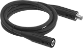 |
The quick-action connectors on these cords give your welding set-up greater versatility by allowing quick changes.
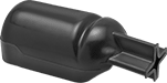
Grounding Clamps for Welding
C-Clamp
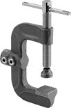 | 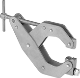 | 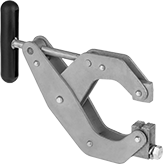 |
Heavy Duty | No Twist | No Twist ABS Plastic Handle |
Current, amp | For No. of Wires | For Wire Ga. | Max. Cable Outlet Dia. | Jaw Opening | Connection Material | Electrical Connection | Cable Connection | Features | Each | |||
|---|---|---|---|---|---|---|---|---|---|---|---|---|
Standard | ||||||||||||
| 300 | — | 1/0, 2/0 | 0.56" | 2" | Bronze | Grounding Clamp | Welding | Copper-Plated Steel Screw | 7840A12 | 000000 | ||
| 300 | — | 1/0, 2/0 | 0.56" | 2" | Bronze | Grounding Clamp | Screw Terminal | Copper-Plated Steel Screw | 7840A13 | 00000 | ||
| 600 | — | 3/0, 4/0 | 0.63" | 2" | Bronze | Grounding Clamp | Welding | Copper-Plated Steel Screw | 7840A15 | 00000 | ||
| 600 | — | 3/0, 4/0 | 0.63" | 2" | Bronze | Grounding Clamp | Screw Terminal | Copper-Plated Steel Screw | 7840A14 | 00000 | ||
Heavy Duty | ||||||||||||
| 600 | 1 | 3/0, 4/0 | 0.66" | 3 3/8" | Bronze | Grounding Clamp | Welding | Copper-Plated Steel Screw | 7840A16 | 000000 | ||
| 600 | 1 | 3/0, 4/0 | 0.66" | 3 3/8" | Bronze | Grounding Clamp | Screw Terminal | Copper-Plated Steel Screw | 7840A11 | 000000 | ||
No Twist | ||||||||||||
| 400 | — | — | — | 4 1/2" | Copper | Grounding Clamp | Stud Terminal | — | 7840A19 | 00000 | ||
| 400 | — | — | — | 4 1/2" | Copper | Grounding Clamp | Stud Terminal | ABS Plastic Handle | 7840A21 | 00000 | ||
Plier Clamp
 | 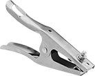 |
Nonconductive |
Plier clamps are good for light duty applications that require mobility, such as building a fence.
Copper Connection—Clamps that are copper prevent weld spatter from sticking.
Nonconductive—Nonconductive clamps won’t transmit electricity, meaning you can touch them while the power is on without disrupting the circuit.
Cable Support—Cable supports prevent cable strand breakage.
Current, amp | For Wire Ga. | Jaw Opening | Connection Material | Electrical Connection | Cable Connection | Stud Lg. | Features | Each | |||
|---|---|---|---|---|---|---|---|---|---|---|---|
| 180 | 1/0 | 2" | Copper | Grounding Clamp | Stud Terminal | 1/2" | Nonconductive, Cable Support | 7838A13 | 000000 | ||
| 200 | 1/0 | 1 1/2" | Steel | Grounding Clamp | Stud Terminal | 3/4" | Cable Support | 7838A14 | 00000 | ||
| 300 | 1/0, 2/0 | 2" | Steel | Grounding Clamp | Stud Terminal | 3/4" | Cable Support | 7838A11 | 00000 | ||
| 500 | 3/0, 4/0 | 2" | Steel | Grounding Clamp | Stud Terminal | 3/4" | Braided Copper Shunt, Cable Support | 7838A12 | 00000 | ||
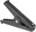
Spring Clamp
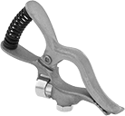 | 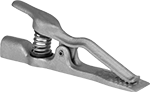 |
Standard | Flat Jaw |
Spring clamps have an extended jaw that eases clamping. Both jaws carry current.
Flat Jaw—Flat-jaw clamps grip flat surfaces especially well. They have a larger contact area with the workpiece than standard spring clamps, so electricity flows more easily, but their jaw openings aren’t as large.
Copper Connection—Clamps that are copper prevent weld spatter from sticking.
Cable Support—Cable supports prevent cable strand breakage.
Current, amp | For Wire Ga. | Max. Cable Outlet Dia. | Jaw Opening | Connection Material | Electrical Connection | Cable Connection | Features | Each | |||
|---|---|---|---|---|---|---|---|---|---|---|---|
Standard | |||||||||||
| 200 | 6, 5, 4, 3, 2, 1, 1/0 | 0.51" | 1" | Copper | Grounding Clamp | Screw Terminal | Copper Hinge Pin, Cable Support | 7991A4 | 000000 | ||
| 300 | 6, 5, 4, 3, 2, 1, 1/0, 2/0, 3/0 | 0.54" | 1 1/2" | Copper | Grounding Clamp | Screw Terminal | Copper Hinge Pin, Cable Support | 7991A5 | 00000 | ||
| 500 | 6, 5, 4, 3, 2, 1, 1/0, 2/0, 3/0, 4/0 | 0.58" | 2" | Copper | Grounding Clamp | Screw Terminal | Copper Hinge Pin, Cable Support | 7991A6 | 00000 | ||
Flat Jaw | |||||||||||
| 200 | 6, 5, 4, 3, 2, 1, 1/0 | — | 5/8" | Copper | Grounding Clamp | Screw Terminal | Copper Hinge Pin | 7840A22 | 00000 | ||
| 300 | 6, 5, 4, 3, 2, 1, 1/0, 2/0, 3/0 | — | 1" | Copper | Grounding Clamp | Screw Terminal | Copper Hinge Pin | 7840A23 | 00000 | ||
| 500 | 6, 5, 4, 3, 2, 1, 1/0, 2/0, 3/0, 4/0 | — | 1 1/4" | Copper | Grounding Clamp | Screw Terminal | Copper Hinge Pin | 7840A24 | 000000 | ||
Magnetic Clamp
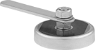 | 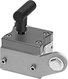 | 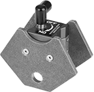 |
Magnetic Clamp | Magnetic Clamp with On/Off Switch | Multiple-Angle Magnetic Clamp with On/Off Switch |
Magnetic clamps stick to metal surfaces on your workpiece, even oddly-shaped and sized ones. Compared to traditional clamps, they require less manual effort and are less limited by the amount of space available on your workpiece. However, you can’t use them on aluminum or nonferrous material, and their hold is usually less powerful than traditional clamps.
Multiple Angle—Multiple-angle clamps let you hold more than one workpiece at a time, at different angles.
Copper Connection—Clamps that are copper prevent weld spatter from sticking.
On/Off Switch—Clamps with an on/off switch let you engage and disengage the magnet for easy placement and removal of your workpiece.
Current, amp | Connection Material | Electrical Connection | Cable Connection | Dia. | Ht. | Wd. | Handle Lg. | Stud Lg. | Features | Each | |||
|---|---|---|---|---|---|---|---|---|---|---|---|---|---|
Standard | |||||||||||||
| 200 | Steel | Grounding Clamp | Stud Terminal | — | 2 3/4" | 1 13/16" | — | 1 1/4" | On/Off Switch | 7992A11 | 000000 | ||
| 250 | Brass | Grounding Clamp | Stud Terminal | 3 1/2" | — | — | 5 1/8" | 2" | — | 7992A1 | 00000 | ||
| 300 | Steel | Grounding Clamp | Stud Terminal | — | 2 3/4" | 1 15/16" | — | 1 1/4" | On/Off Switch | 7992A6 | 00000 | ||
| 800 | Copper | Grounding Clamp | Stud Terminal | 3 1/2" | — | — | 5 1/8" | 2" | — | 7992A5 | 00000 | ||
| 800 | Steel | Grounding Clamp | Stud Terminal | — | 5" | 3" | — | 1 1/4" | On/Off Switch | 7992A8 | 000000 | ||
Multiple Angle | |||||||||||||
| 300 | Steel | Grounding Clamp | Stud Terminal | — | 3 3/4" | 1 15/16" | — | — | On/Off Switch | 7992A12 | 000000 | ||
Solder and Compression Welding Lug Assortments
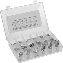 |
Keep a variety of welding lug sizes on hand. Either solder these welding lugs into place, or use a hammer-on crimper (not included) for a secure connection.
No. of Pieces | Includes | For Wire Material | For Wire Construction | Terminal Material | Max. Temp., ° F | Max. Voltage, V DC | Each | |||
|---|---|---|---|---|---|---|---|---|---|---|
1 Hole—For 1 Wire | ||||||||||
| 68 | 6 AWG for 1/4", 5/16" and 3/8" Screws, 4 AWG for 1/4", 5/16", 3/8" and 1/2" Screws, 2 AWG, 1/0-4/0 for 3/8" and 1/2" Screws; Plastic Compartmented Case | Copper | Stranded | Copper | 190 | 48 | 4189N11 | 000000 | ||
Welding Lug Covers
 |
For Wire Ga. | Material | For Lug Shape | Each | ||
|---|---|---|---|---|---|
| 6, 4, 2, 1, 1/0, 2/0, 3/0, 4/0 | Vinyl Plastic | Straight | 7828A11 | 000000 |
Abrasion-Resistant Extension Cords
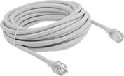 |
Our most durable extension cords. Built to NEC Article 400 standards for extra-hard service, these cords resist wear that could expose conductors and compromise safety. Their thick jacket protects against scrapes from rough surfaces.
Power Indicator—A light indicates that power is flowing through the cord.
Ground-Presence Indicator—A light indicates that the cord is properly grounded.
Hammer-On Welding Lugs
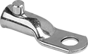 |
Slide these welding lugs onto cable and strike them with your hammer to create a durable connection.
For Wire Ga. | For Screw Size | For Screw Size Decimal Equiv. | For Wire Construction | For Wire Material | Lg. | Wd. | Ht. | Thk. | Terminal Material | Max. Temp. | Max. Voltage | Each | |||
|---|---|---|---|---|---|---|---|---|---|---|---|---|---|---|---|
Straight | |||||||||||||||
1 Hole—For 1 Wire | |||||||||||||||
| 1, 1/0, 2/0 | 1/2" | 0.500" | Stranded | Aluminum, Copper | 2.875" | 1" | 0.75" | 0.15" | Copper | Not Rated | Not Rated | 69575K3 | 00000 | ||
| 3/0, 4/0 | 1/2" | 0.500" | Stranded | Aluminum, Copper | 3.156" | 1.156" | 0.906" | 0.18" | Copper | Not Rated | Not Rated | 69575K4 | 00000 | ||
|
For Wire Ga. | Material | Each | ||
|---|---|---|---|---|
| 6, 4, 2, 1, 1/0, 2/0, 3/0, 4/0 | Vinyl Plastic | 7828A11 | 000000 |
Ready-to-Use Welding Cords with Male Connector and Electrode Holder
Tight-Hold Compression Lugs
These prevent pullout better than other compression lugs, and they give you more options for attaching the wire. To attach with solder, heat the enclosed solder onto your stranded wire. This bonds the wire to the lug for a secure hold and a continuous, ultra-conductive metallic connection. If sharp bends and tugs aren't a concern, you can skip the soldering and use a compression tool to squeeze the barrel tightly and evenly onto the wire. Compression lugs are a step up from set screw lugs when you need a physically strong connection, though set screw lugs attach to even larger wire.
For Wire Ga. | For Screw Size | Lg. | Wd. | Ht. | Thk. | For Wire Construction | For Wire Material | Terminal Material | Max. Temp. | Max. Voltage | Each | |||
|---|---|---|---|---|---|---|---|---|---|---|---|---|---|---|
Solder and Compression Connection | ||||||||||||||
| 8 to 6 | 5/16" | 1.39" | 0.539" | 0.380" | 0.08" | Stranded | Copper | Copper | Not Rated | Not Rated | 7913A41 | 00000 | ||
| 6 to 4 | 5/16" | 1.6" | 0.622" | 0.450" | 0.1" | Stranded | Copper | Copper | Not Rated | Not Rated | 7913A42 | 0000 | ||
Welding Cable Connector Sets
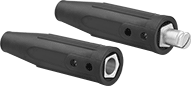 |
Each set includes one plug and one socket. Plugs lock into sockets with a cam action that pulls the two pieces together tightly. The housing resists oil.
Mated Housing | |||||||||||
|---|---|---|---|---|---|---|---|---|---|---|---|
Current, amp | Wire Connection | For Wire Ga. | For Cable OD | Housing Connection Method | Dia. | Lg. | Color | Temp. Range, ° F | Each | ||
| 250 | Screw Terminal | 4, 3, 2, 1, 1/0 | 0.2" to 0.5" | Push In | 1.3" | 9.7" | Black | -50 to 350 | 7841A11 | 000000 | |
| 350 | Screw Terminal | 1/0, 2/0 | 0.32" to 0.56" | Push In | 1.4" | 9.8" | Black | -50 to 350 | 7841A12 | 00000 | |
| 500 | Screw Terminal | 3/0, 4/0 | 0.41" to 0.63" | Push In | 1.4" | 9.8" | Black | -50 to 350 | 7841A13 | 00000 | |
Solder and Compression Welding Lugs
 |
Solder these welding lugs in place, or use a crimping tool (not included) for a secure connection.
For Wire Ga. | For Screw Size | For Screw Size Decimal Equiv. | For Wire Construction | For Wire Material | Lg. | Wd. | Ht. | Thk. | Terminal Material | Max. Temp. | Max. Voltage | Each | |||
|---|---|---|---|---|---|---|---|---|---|---|---|---|---|---|---|
Straight | |||||||||||||||
1 Hole—For 1 Wire | |||||||||||||||
| 6, 4, 2 | 1/2" | 0.500" | Stranded | Copper | 2.67" | 0.78" | 0.63" | 0.12" | Copper | Not Rated | 80V AC 80V DC | 7913A1 | 00000 | ||
| 1, 1/0, 2/0 | 1/2" | 0.500" | Stranded | Copper | 2.89" | 1" | 0.768" | 0.15" | Copper | Not Rated | 80V AC 80V DC | 7913A2 | 0000 | ||
| 3/0, 4/0 | 1/2" | 0.500" | Stranded | Copper | 3.15" | 1.17" | 0.89" | 0.16" | Copper | Not Rated | 80V AC 80V DC | 7913A3 | 00000 | ||
| 4/0 | 5/8" | 0.625" | Stranded | Copper | 3.87" | 1.36" | 1.02" | 0.17" | Copper | Not Rated | 80V AC 80V DC | 7913A4 | 00000 | ||
|
For Wire Ga. | Material | Each | ||
|---|---|---|---|---|
| 6, 4, 2, 1, 1/0, 2/0, 3/0, 4/0 | Vinyl Plastic | 7828A11 | 000000 |
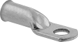
Insulated Set Screw Welding Lugs
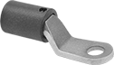 | 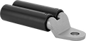 | 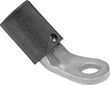 |
Straight 1 Hole—For 1 Wire | Straight 1 Hole—For 2 Wires | 45° Elbow |
To prevent short-circuiting with nearby wire, a plastic cover insulates the barrel on these welding lugs. Tighten the set screw for a secure connection without crimping.
45° Elbow—45° elbow lugs connect to wire at an angle, so they fit in tight spaces.
For Wire Ga. | For Screw Size | For Screw Size Decimal Equiv. | For Wire Construction | For Wire Material | Lg. | Wd. | Ht. | Thk. | Insulation Color | Insulation Material | Terminal Material | Max. Temp., ° F | Max. Voltage | Each | |||
|---|---|---|---|---|---|---|---|---|---|---|---|---|---|---|---|---|---|
Straight | |||||||||||||||||
1 Hole—For 1 Wire | |||||||||||||||||
| 6, 4, 2, 1, 1/0 | 1/2" | 0.500" | Stranded | Copper | 3.625" | 1.054" | 1.270" | 0.2" | Black | Nylon | Copper | 470 | 40V AC 40V DC | 7866A12 | 000000 | ||
| 2/0, 3/0, 4/0 | 1/2" | 0.500" | Stranded | Copper | 3.625" | 1.080" | 1.520" | 0.188" | Black | Nylon | Copper | 470 | 40V AC 40V DC | 7866A14 | 00000 | ||
1 Hole—For 2 Wires | |||||||||||||||||
| 2/0, 3/0, 4/0 | 5/8" | 0.625" | Stranded | Copper | 6.875" | 2.687" | 1.562" | 0.257" | Black | Nylon | Copper | 350 | 40V AC 40V DC | 7866A15 | 00000 | ||
45° Elbow | |||||||||||||||||
1 Hole—For 1 Wire | |||||||||||||||||
| 6, 4, 2, 1, 1/0 | 1/2" | 0.500" | Stranded | Copper | 3.125" | 1.073" | 1.750" | 0.215" | Black | Nylon | Copper | 470 | 40V AC 40V DC | 7866A11 | 00000 | ||
| 2/0, 3/0, 4/0 | 1/2" | 0.500" | Stranded | Copper | 3.375" | 0.913" | 1.991" | 0.188" | Black | Nylon | Copper | 470 | 40V AC 40V DC | 7866A13 | 00000 | ||
|
For Wire Ga. | Material | Each | ||
|---|---|---|---|---|
| 6, 4, 2, 1, 1/0, 2/0, 3/0, 4/0 | Vinyl Plastic | 7828A11 | 000000 |
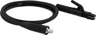
Ready-to-Use Welding Cords with Male Connector and Grounding Clamp
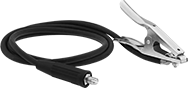 |
The male quick-action connector on these cords gives your welding set-up greater versatility by allowing quick changes.
Stranded Wire Class K—Stranded Wire Class K cords are good for general welding applications.
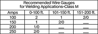
Stranded Wire Class M—Stranded Wire Class M cords are often used in pipe welding because they’re more flexible and durable than Stranded Wire Class K cords.
Cable AWG | AWG | Welding Process | No. of Wires | Outer Jacket Material | 10 ft. Long | 25 ft. Long | 50 ft. Long | |||
|---|---|---|---|---|---|---|---|---|---|---|
Stranded Wire Class K | ||||||||||
Black Outer Jacket | ||||||||||
| 1/0/1 | 1/0 | MIG, TIG, Stick, Spot, Stud | 1 | EPDM | 7940A31 | 0000000 | 0000000 | 0000000 | ||
| 2/0/1 | 2/0 | MIG, TIG, Stick, Spot, Stud | 1 | EPDM | 7940A33 | 000000 | 000000 | 000000 | ||
Red Outer Jacket | ||||||||||
| 1/0/1 | 1/0 | MIG, TIG, Stick, Spot, Stud | 1 | EPDM | 7940A844 | 000000 | 000000 | 000000 | ||
| 2/0/1 | 2/0 | MIG, TIG, Stick, Spot, Stud | 1 | EPDM | 7940A846 | 000000 | 000000 | 000000 | ||
Stranded Wire Class M | ||||||||||
Orange/Black Outer Jacket | ||||||||||
| 1/0/1 | 1/0 | MIG, TIG, Stick, Spot, Stud | 1 | TPE | 7940A845 | 000000 | 000000 | 000000 | ||
| 2/0/1 | 2/0 | MIG, TIG, Stick, Spot, Stud | 1 | TPE | 7940A847 | 000000 | 000000 | 000000 | ||
Flame-Resistant Welding Cable
 | |
Outer Jacket | Per Ft. | ||||||||||||
|---|---|---|---|---|---|---|---|---|---|---|---|---|---|
AWG | Stranded Wire Class | Wire Strand Count | Material | Color | Temp., ° F | Flammability Rating | Certification | Choose a Length, ft. | 1-249 | 250-Up | |||
600V AC/600V DC | |||||||||||||
Flexible | |||||||||||||
| 6 | M | 660/34 | Polyethylene | Orange | -55 to 190 | UL 2556 VW-1 | CSA Certified, MSHA Accepted, UL Listed | 10, 20, 25, 30, 50, 100, 250 | 7818A18 | 00000 | 00000 | ||
| 4 | M | 1,045/34 | Polyethylene | Orange | -55 to 190 | UL 2556 VW-1 | CSA Certified, MSHA Accepted, UL Listed | 10, 20, 25, 30, 50, 100, 250 | 7818A11 | 0000 | 0000 | ||
| 2 | M | 1,634/34 | Polyethylene | Orange | -55 to 190 | UL 2556 VW-1 | CSA Certified, MSHA Accepted, UL Listed | 10, 20, 25, 30, 50, 100, 250 | 7818A12 | 00000 | 0000 | ||
| 1/0 | M | 2,597/34 | Polyethylene | Orange | -55 to 190 | UL 2556 VW-1 | CSA Certified, MSHA Accepted, UL Listed | 10, 20, 25, 30, 50, 100, 250 | 7818A14 | 00000 | 00000 | ||
| 2/0 | M | 3,300/34 | Polyethylene | Orange | -55 to 190 | UL 2556 VW-1 | CSA Certified, MSHA Accepted, UL Listed | 10, 20, 25, 30, 50, 100, 250 | 7818A15 | 00000 | 00000 | ||
| 3/0 | M | 4,214/34 | Polyethylene | Orange | -55 to 190 | UL 2556 VW-1 | CSA Certified, MSHA Accepted, UL Listed | 10, 20, 25, 30, 50, 100, 250 | 7818A16 | 00000 | 00000 | ||
| 4/0 | M | 5,225/34 | Polyethylene | Orange | -55 to 190 | UL 2556 VW-1 | CSA Certified, MSHA Accepted, UL Listed | 10, 20, 25, 30, 50, 100, 250 | 7818A17 | 00000 | 00000 | ||
