


Filter by
System of Measurement
Current @ Temperature
Shielding
Wire and Cable Use
Wire Finish
Minimum Temperature
Cable AWG
DFARS Specialty Metals
Export Control Classification Number (ECCN)

About Wire and Cable
Compare wire vs. cable and choose the right option based on gauge, number of conductors, insulation, and current rating.
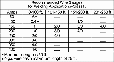
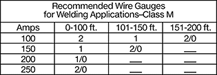
Welding Cable
 |
 |
AWG | Stranded Wire Class | Wire Strand Count | Current @ Temp. | Outer Jacket Material | Temp., ° F | Flammability Rating | Choose an Outer Jacket Color | Choose a Length, ft. | Per Ft. | |||
|---|---|---|---|---|---|---|---|---|---|---|---|---|
600V AC | ||||||||||||
Bend and Stay | ||||||||||||
| 1 | K | 767/30 | — | EPDM | -55 to 220 | UL 2556 VW-1 | Black, Red | 10, 20, 25, 30, 50, 100, 250 | 7940A94 | 00000 | ||
600V AC/600V DC | ||||||||||||
Flexible | ||||||||||||
| 1 | M | 1,843/34 | — | EPDM | -55 to 220 | UL 2556 VW-1 | Orange | 10, 20, 25, 30, 50, 100, 250 | 7940A78 | 0000 | ||
Ultra Flexible | ||||||||||||
| 1 | — | 798/30 | 220 amp @ 86° F | EPDM | -40 to 190 | — | Black, Red | 10, 25, 50, 100 | 6948K94 | 0000 | ||
Aluminum Building Wire
Mend or extend aluminum wire often found in older buildings. This wire isn’t recommended for new wiring, since it’s more likely to overheat than copper when conducting electricity. However, it’s safer to maintain existing aluminum wire with aluminum rather than mixing materials. Building wire is also known as branch circuit wire.
This wire has an outer layer of nylon insulation that won't degrade from oil and water. It’s designed to be pulled through conduit without pulling lubricants. THHN and THWN-2 designated, this wire can be used in damp places.
AWG | Current @ Temp. | OD | Temp. Range, ° F | Outer Jacket Color | Cable Designation | Certification | 25 ft. Long | 50 ft. Long | 100 ft. Long | 250 ft. Long | 500 ft. Long | |||
|---|---|---|---|---|---|---|---|---|---|---|---|---|---|---|
Stranded Wire with Nylon Outer Jacket and PVC Inner Insulation | ||||||||||||||
600V AC/600V DC | ||||||||||||||
| 1 | 115 amp @ 86° F | 0.41" | -40 to 190 | Black | THHN, THWN-2 | UL Listed | 6082N14 | 000000 | 000000 | 0000000 | 0000000 | 0000000 | ||
Battery Wire
Stranded Wire with PVC Outer Jacket
Wire with a PVC outer jacket resists fuel and oil.
SAE J1127—SAE wire meets standards for low-voltage wiring in vehicle electrical systems.
Wire Strand Count—Wire strand count is the number of strands followed by the size of the individual strand.
Continuous-Flex Power Cable
Unshielded | Shielded |
Power motors on moving gantries and cranes with this cable that flexes millions of times without breaking. It’s made for constant motion, with finely stranded conductors twisted like a rope to resist wear from bending.
Shielded—Shielding stops these cables from acting as antennas that emit electromagnetic interference, which could disrupt nearby equipment such as control or data cables.
Outer Jacket | Per Ft. | |||||||||||||
|---|---|---|---|---|---|---|---|---|---|---|---|---|---|---|
Cable AWG | Current @ Temp. | Bend Radius | Material | Color | Temp., ° F | Flammability Rating | Certification | Clean Room Std. | Choose a Length, ft. | 1-99 | 100-Up | |||
1,000V AC | ||||||||||||||
Unshielded | ||||||||||||||
| 1/4 | 191 amp @ 86° F | 10.35" | PVC | Black | 25 to 155 | UL 2556 VW-1 | C-UL Recognized Component, UL Recognized Component | ISO Class 2 | 5, 10, 20, 30, 50, 100 | 9243K24 | 000000 | 000000 | ||
Shielded | ||||||||||||||
| 1/4 | 191 amp @ 86° F | 11.1" | PVC | Black | 25 to 155 | UL 2556 VW-1 | C-UL Recognized Component, UL Recognized Component | ISO Class 2 | 5, 10, 20, 30, 50, 100 | 9243K44 | 00000 | 00000 | ||
Battery Power Cords
Terminal Clamp × Lug
Terminal Clamp × Lug and Lug with Terminal × Lug cords also connect batteries to electrical systems.
Cord | |||||||||||
|---|---|---|---|---|---|---|---|---|---|---|---|
AWG | Lg. | Lug ID | End Shape | OD | Insulation Material | Connection Material | Temp. Range, ° F | Choose a Color (Polarity) | Each | ||
| 1 | 10" | 3/8" | Straight | 0.49" | PVC | Tin-Plated Copper | -40 to 220 | Black (Negative), Red (Positive) | 69735K41 | 000000 | |
| 1 | 20" | 3/8" | Straight | 0.49" | PVC | Tin-Plated Copper | -40 to 220 | Black (Negative), Red (Positive) | 69735K42 | 00000 | |
| 1 | 30" | 3/8" | Straight | 0.49" | PVC | Tin-Plated Copper | -40 to 220 | Black (Negative), Red (Positive) | 69735K43 | 00000 | |
| 1 | 60" | 3/8" | Straight | 0.49" | PVC | Tin-Plated Copper | -40 to 220 | Black (Negative), Red (Positive) | 69735K44 | 00000 | |
Lug with Terminal × Lug
Terminal Clamp × Lug and Lug with Terminal × Lug cords also connect batteries to electrical systems.
Cord | |||||||||||
|---|---|---|---|---|---|---|---|---|---|---|---|
AWG | Lg. | Lug ID | End Shape | OD | Insulation Material | Connection Material | Temp. Range, ° F | Choose a Color (Polarity) | Each | ||
| 1 | 10" | 3/8" | Straight | 0.49" | PVC | Tin-Plated Copper | -40 to 220 | Black (Negative), Red (Positive) | 69735K26 | 000000 | |
| 1 | 20" | 3/8" | Straight | 0.49" | PVC | Tin-Plated Copper | -40 to 220 | Black (Negative), Red (Positive) | 69735K27 | 00000 | |
| 1 | 30" | 3/8" | Straight | 0.49" | PVC | Tin-Plated Copper | -40 to 220 | Black (Negative), Red (Positive) | 69735K28 | 00000 | |
| 1 | 60" | 3/8" | Straight | 0.49" | PVC | Tin-Plated Copper | -40 to 220 | Black (Negative), Red (Positive) | 69735K29 | 00000 | |
Braided Grounding Straps
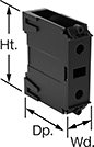
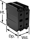
Distribution Blocks
Screw-Clamp Terminal Input Connection
 |
Blocks with a screw-clamp terminal input wire connection have a current rating based on NEC table 310-16 using 75° C copper wire.
Extendable—Extendable blocks attach to each other to create custom-sized distribution blocks.
Detachable Cover—Blocks with a detachable cover prevent accidental contact with live circuits.
No. of Connections Per Circuit | ||||||||||||||
|---|---|---|---|---|---|---|---|---|---|---|---|---|---|---|
Current per Circuit, amp | Voltage | Input (For Wire Ga.) | Output (For Wire Ga.) | Wd. | Ht. | Dp. | Enclosure Rating | Certification | Flammability Rating | Features | Each | |||
DIN-Rail Mount | ||||||||||||||
1 Circuit | ||||||||||||||
| 175 | 600V AC/600V DC | 1 (14-2/0) | 1 (14-2/0) | 1" | 3" | 2 9/16" | — | UL Recognized Component, CSA Certified, CE Marked | UL 94 V-0 | Detachable Cover | 6367T11 | 000000 | ||
2 Circuits | ||||||||||||||
| 175 | 600V AC/600V DC | 1 (14-2/0) | 1 (14-2/0) | 2" | 3" | 2 9/16" | — | UL Recognized Component, CSA Certified, CE Marked | UL 94 V-0 | Detachable Cover | 6367T12 | 00000 | ||
3 Circuits | ||||||||||||||
| 175 | 600V AC/600V DC | 1 (14-2/0) | 1 (14-2/0) | 2 5/8" | 3" | 2 9/16" | — | UL Recognized Component, CSA Certified, CE Marked | UL 94 V-0 | Detachable Cover | 6367T13 | 00000 | ||
Surface Mount | ||||||||||||||
1 Circuit | ||||||||||||||
| 760 | 600V AC | 2 (4-4/0) | 8 (14- 2/0) | 2 1/2" | 4.63" | 3 3/8" | IP20 | UL Listed, CSA Certified, CE Marked | UL 94 V-0 | Extendable | 6367T45 | 000000 | ||
Stud-Terminal Input Connection
 |
Detachable Cover—Blocks with a detachable cover prevent accidental contact with live circuits.
No. of Connections Per Circuit | ||||||||||||||
|---|---|---|---|---|---|---|---|---|---|---|---|---|---|---|
Current per Circuit, amp | Voltage | Input (For Wire Ga.) | Output (For Wire Ga.) | Terminal Size | Wd. | Ht. | Dp. | Certification | Flammability Rating | Features | Each | |||
DIN-Rail Mount | ||||||||||||||
1 Circuit | ||||||||||||||
| 200 | 600V AC/600V DC | 1 (14-3/0) | 1 (14-3/0) | 1/4" | 1" | 3" | 2 9/16" | UL Recognized Component, CSA Certified, CE Marked | UL 94 V-0 | Detachable Cover | 6367T34 | 000000 | ||
2 Circuits | ||||||||||||||
| 200 | 600V AC/600V DC | 1 (14-3/0) | 1 (14-3/0) | 1/4" | 2" | 3 1/8" | 3 1/4" | UL Recognized Component, CSA Certified, CE Marked | UL 94 V-0 | Detachable Cover | 6367T35 | 00000 | ||
3 Circuits | ||||||||||||||
| 200 | 600V AC/600V DC | 1 (14-3/0) | 1 (14-3/0) | 1/4" | 2 9/16" | 3 1/8" | 3 1/4" | UL Recognized Component, CSA Certified, CE Marked | UL 94 V-0 | Detachable Cover | 6367T36 | 00000 | ||
Surface Mount | ||||||||||||||
1 Circuit | ||||||||||||||
| 310 | 600V AC/600V DC | 1 (14-4/0) | 1 (14-4/0) | 3/8" | 2" | 4" | 3 1/2" | UL Recognized Component, CSA Certified | UL 94 V-0 | Detachable Cover | 6367T37 | 00000 | ||
2 Circuits | ||||||||||||||
| 310 | 600V AC/600V DC | 1 (14-4/0) | 1 (14-4/0) | 3/8" | 3 5/8" | 4" | 3 1/2" | UL Recognized Component, CSA Certified | UL 94 V-0 | Detachable Cover | 6367T38 | 000000 | ||
3 Circuits | ||||||||||||||
| 310 | 600V AC/600V DC | 1 (14-4/0) | 1 (14-4/0) | 3/8" | 5 3/8" | 4" | 3 1/2" | UL Recognized Component, CSA Certified | UL 94 V-0 | Detachable Cover | 6367T39 | 000000 | ||
Easy-Insert Lay-In Wire Taps
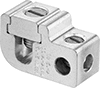 |  |
Covers |
Lay the main wire into your tap on the first try instead of poking and threading. The tap wire connects parallel to the tap or at 90°, so the tap will slide into your setup at different angles. Strip both wires and slide off the screw plate before installation. Tighten the set screws onto both wires for a secure connection.
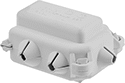
Covers—These covers fully insulate the tap so moisture can't reach the wire. They snap shut so you don't have to tape them down.
Wire Taps | Covers | ||||||||||||
|---|---|---|---|---|---|---|---|---|---|---|---|---|---|
For Wire | For Tap Wire | ||||||||||||
Ga. | Construction | Material | Ga. | Construction | Terminal Material | Max. Temp., ° F | Max. Voltage, V AC | Certification | Each | Each | |||
| 2 to 1/0 12 to 10 | Stranded Solid | Aluminum, Copper | 12 to 1/0 12 to 1/0 | Stranded Solid | Tin-Plated Aluminum | 190 | 600 | CSA Certified, UL Listed | 4296N12 | 000000 | 4296N15 | 00000 | |
| 1/0 to 250 MCM 12 to 10 | Stranded Solid | Aluminum, Copper | 12 to 1/0 12 to 1/0 | Stranded Solid | Tin-Plated Aluminum | 190 | 600 | CSA Certified, UL Listed | 4296N13 | 00000 | 4296N16 | 00000 | |
Jumper Cables
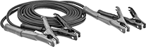 |
These cables have thick wires for a fast start on large trucks and industrial vehicles. The clamps are color-coded black (negative) and red (positive).
Wire | Clamp | ||||||||||
|---|---|---|---|---|---|---|---|---|---|---|---|
Lg., ft. | Max. Current, amp | AWG | Construction | Material | Insulation Material | Material | Insulation Material | Temp. Range, ° F | Pair | ||
| 12 | 800 | 1 | Stranded | Copper | TPE | Metal | PVC | -40 to 175 | 7234K62 | 0000000 | |
| 16 | 800 | 1 | Stranded | Copper | TPE | Metal | PVC | -40 to 175 | 7234K63 | 000000 | |
| 20 | 800 | 1 | Stranded | Copper | TPE | Metal | PVC | -40 to 175 | 7234K49 | 000000 | |
| 25 | 800 | 1 | Stranded | Copper | TPE | Metal | PVC | -40 to 175 | 7234K46 | 000000 | |
