



























Filter by
Product Family
Actuator Style


Wire Connection


Electrical Connection


Switch Type


Switch Starting Position

Switch Action
Pull Direction


Switch Designation

U.S.–Mexico–Canada Agreement (USMCA) Qualifying
DFARS Specialty Metals
Export Control Classification Number (ECCN)

About Electrical Switches
%20--%3e%3csvg%20version='1.1'%20id='Layer_1'%20xmlns='http://www.w3.org/2000/svg'%20xmlns:xlink='http://www.w3.org/1999/xlink'%20x='0px'%20y='0px'%20viewBox='0%200%20400%20400'%20style='enable-background:new%200%200%20400%20400;'%20xml:space='preserve'%3e%3cstyle%20type='text/css'%3e%20.st0{fill:%231A70A0;}%20.st1{opacity:0.5;}%20%3c/style%3e%3cg%3e%3cg%3e%3cpath%20class='st0'%20d='M200,56.9c38.35,0,74.4,14.93,101.51,42.05c27.11,27.11,42.05,63.17,42.05,101.51s-14.93,74.4-42.05,101.51%20S238.35,344.02,200,344.02s-74.4-14.93-101.51-42.05c-27.11-27.11-42.05-63.17-42.05-101.51s14.93-74.4,42.05-101.51%20S161.65,56.9,200,56.9%20M200,12.9C96.41,12.9,12.44,96.88,12.44,200.46c0,103.59,83.97,187.56,187.56,187.56%20c103.59,0,187.56-83.97,187.56-187.56C387.56,96.88,303.59,12.9,200,12.9L200,12.9z'/%3e%3c/g%3e%3cg%3e%3cg%20class='st1'%3e%3cpath%20class='st0'%20d='M235.49,152.24h16.15l-27.46,111.87c-1.94,7.8-2.91,12.5-2.91,14.1c0,1.82,0.58,3.29,1.73,4.41%20c1.16,1.12,2.69,1.68,4.61,1.68c5.23,0,11.78-3.85,19.63-11.55l17.22,21.34c-16.95,17.33-34.87,26-53.78,26%20c-8.37,0-15.45-1.47-21.23-4.41c-5.79-2.94-10.44-7.25-13.95-12.92c-3.51-5.67-5.27-11.18-5.27-16.53c0-1.93,0.35-5.24,1.05-9.94%20c1-6.94,2.05-12.54,3.15-16.82l15.22-62.15h-32.69l7.65-30.97C190.89,163.58,214.53,158.88,235.49,152.24z%20M230.44,80.84%20c8.24,0,14.66,2.62,19.26,7.86c4.6,5.24,6.9,11.55,6.9,18.94c0,5.46-1.42,10.7-4.25,15.73c-2.83,5.03-6.88,9.07-12.12,12.12%20c-5.24,3.05-10.33,4.57-15.24,4.57c-4.6,0-9.17-1.23-13.72-3.69c-4.55-2.46-8.02-5.78-10.43-9.95%20c-2.41-4.17-3.61-8.67-3.61-13.48c0-5.35,1.52-10.64,4.57-15.89c3.05-5.24,7.03-9.25,11.96-12.04%20C218.68,82.23,224.24,80.84,230.44,80.84z'/%3e%3c/g%3e%3cg%3e%3cpath%20class='st0'%20d='M214.08,152.24h16.15l-27.46,111.87c-1.94,7.8-2.91,12.5-2.91,14.1c0,1.82,0.58,3.29,1.73,4.41%20c1.16,1.12,2.69,1.68,4.61,1.68c5.23,0,11.78-3.85,19.63-11.55l17.22,21.34c-16.95,17.33-34.87,26-53.78,26%20c-8.37,0-15.45-1.47-21.23-4.41c-5.79-2.94-10.44-7.25-13.95-12.92c-3.51-5.67-5.27-11.18-5.27-16.53c0-1.93,0.35-5.24,1.05-9.94%20c1-6.94,2.05-12.54,3.15-16.82l15.22-62.15h-32.69l7.65-30.97C169.48,163.58,193.11,158.88,214.08,152.24z%20M209.03,80.84%20c8.24,0,14.66,2.62,19.26,7.86c4.6,5.24,6.9,11.55,6.9,18.94c0,5.46-1.42,10.7-4.25,15.73c-2.83,5.03-6.88,9.07-12.12,12.12%20c-5.24,3.05-10.33,4.57-15.24,4.57c-4.6,0-9.17-1.23-13.72-3.69c-4.55-2.46-8.02-5.78-10.43-9.95%20c-2.41-4.17-3.61-8.67-3.61-13.48c0-5.35,1.52-10.64,4.57-15.89c3.05-5.24,7.03-9.25,11.96-12.04%20C197.26,82.23,202.83,80.84,209.03,80.84z'/%3e%3c/g%3e%3c/g%3e%3c/g%3e%3c/svg%3e)
Choose a switch with the right trigger type, number of inputs, and control functions to power your equipment.
Pull-Chain Switches
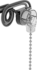 |
Pull the chain to send a switch signal. These switches are commonly used as replacements in lights and fans.
Wire Leads | |||||||||||||||||
|---|---|---|---|---|---|---|---|---|---|---|---|---|---|---|---|---|---|
Chain Lg. | No. of Circuits Controlled | Switch Starting Position | Switch Action | No. of Terminals | Switch Designation | Switching Current @ Voltage | Max. Voltage, V AC | Ht. | Wd. | Dp. | No. of | Lg. | Certification | Each | |||
Wire Lead Connection | |||||||||||||||||
| 2" | 2 | 2 On | Maintained | 4 | DPST-NC | 6 amp @ 125V AC, 3 amp @ 250V AC | 250 | 1 1/8" | 3/4" | 1 3/8" | 3 | 6" | UL Recognized Component | 6969N11 | 00000 | ||
Cable-Pull-Actuator Emergency Stop Switches
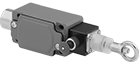 | 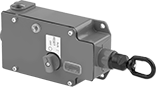 |
1 Direction (IP65, NEMA 4) | 1 Direction with Power Indicator and Tension Indicator (IP67, NEMA 4, NEMA 13) |
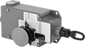 | 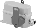 |
1 Direction with Emergency Stop Button, Power Indicator and Tension Indicator (IP67, NEMA 4, NEMA 13) | 2 Directions (IP67) |
Immediately cut power by pulling a cable. These switches are often used to turn off production lines and material handling systems in an emergency. All have positive-force, snap-open contacts that open a circuit when actuated, even if a spring fails or the contacts stick. The contacts will remain open until you tension the cable and reset the switch.
2 Directions—Two-direction switches can be used with tension springs (not included) to open contacts and stop machinery if the cable breaks.
Emergency Stop Button—Switches with an emergency stop button can be shut off either by their button or cable. They’re often installed where equipment may block access to the cable.
Power Indicator—Switches with a power indicator illuminate when the cable has been pulled.
Tension Indicator—Switches with a tension indicator let you visually confirm that tension is set correctly in the system.
Switch Installation Kits—Accessory kits (sold separately) simplify the installation of a new switch.
Emergency Stop Switches | Switch Installation Kits | |||||||||||||||||
|---|---|---|---|---|---|---|---|---|---|---|---|---|---|---|---|---|---|---|
Mounting | ||||||||||||||||||
For Max. Cable Lg., ft. | No. of Circuits Controlled | Switch Starting Position | No. of Terminals | Switch Designation | Switching Current @ Voltage | Max. Voltage | Actuation Force, lbf | Conduit Trade Size | Fasteners Included | Hole Dia. | No. of Holes | Each | Includes | Each | ||||
Screw-Terminal Wire Connection | ||||||||||||||||||
1 Direction (IP65, NEMA 4) | ||||||||||||||||||
| 15 | 1 | 1 Off and 1 On | 4 | DPST-1NO/1NC | 10 amp @ 120V AC | 400V AC | 18 | 1/2 | No | 1/4" | 4 | 65975K51 | 0000000 | Cable, Clamps, Tension Screws, Thimbles | 65975K81 | 0000000 | ||
| 30 | 1 | 1 Off or 1 On | 3 | SPDT | 10 amp @ 120V AC | 380V AC | 27 | 1/2 | No | 1/4" | 4 | 65975K62 | 000000 | Cable, Clamps, Tension Screws, Thimbles | 65975K82 | 000000 | ||
| 75 | 2 | 2 Off or 2 On | 6 | DPDT | 10 amp @ 120V AC | 380V AC | 45 | 1/2 | No | 1/4" | 4 | 65975K63 | 000000 | Cable, Clamps, Tension Screws, Thimbles | 65975K83 | 000000 | ||
1 Direction with Power Indicator and Tension Indicator (IP67, NEMA 4, NEMA 13) | ||||||||||||||||||
| 250 | 1 | 1 Off or 1 On | 3 | SPDT | 6 amp @ 120V AC 2.8 amp @ 24V DC | 300V AC 250V DC | 40 | 1/2 | No | 1/4" | 4 | 65975K75 | 000000 | — | ——— | 0 | ||
1 Direction with Emergency Stop Button, Power Indicator and Tension Indicator (IP67, NEMA 4, NEMA 13) | ||||||||||||||||||
| 250 | 1 | 1 Off or 1 On | 3 | SPDT | 6 amp @ 120V AC 2.8 amp @ 24V DC | 300V AC 250V DC | 40 | 1/2 | No | 1/4" | 4 | 65975K11 | 000000 | — | ——— | 0 | ||
2 Directions (IP67) | ||||||||||||||||||
| 165 | 2 | 1 Off and 1 On | 4 | DPST-1NO/1NC | 1.1 amp @ 120V AC | 240V AC | 5 | 3/4 | No | 5/16" | 2 | 65975K84 | 000000 | Cable, Clamps, Eyebolts, Tension Screws, Tension Springs | 65975K94 | 000000 | ||
Overhead Rope-Pull Switches
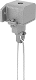 | 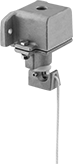 |
Down Pull | Any-Direction Pull |
Tug the hanging rope to actuate these switches. They're rated NEMA 4 to protect against washdowns.
Down Pull—Pull-down switches only actuate when you pull the rope directly down.
Any-Direction Pull—Pull-any-direction switches actuate even when you pull the rope at an angle. These are good for spaces where you can't mount the switch directly above your workstation.
Rope Lg., ft. | No. of Circuits Controlled | Switch Starting Position | Switch Action | No. of Terminals | Switch Designation | Switching Current @ Voltage | Max. Voltage | Actuation Force, lbf | Conduit Trade Size | Mounting Fasteners Included | Certification | Each | |||
|---|---|---|---|---|---|---|---|---|---|---|---|---|---|---|---|
Down Pull | |||||||||||||||
Screw-Terminal Wire Connection | |||||||||||||||
| 15 | 2 | 1 Off and 1 On | Momentary | 4 | DPST-1NO/1NC | 6 amp @ 120V AC, 3 amp @ 240V AC, 0.5 amp @ 125V DC | 600V AC 600V DC | 5 | 1/2 | Yes | UL Listed | 8488K11 | 0000000 | ||
Any-Direction Pull | |||||||||||||||
Screw-Terminal Wire Connection | |||||||||||||||
| 15 | 2 | 1 Off and 1 On | Momentary | 4 | DPST-1NO/1NC | 6 amp @ 120V AC, 3 amp @ 240V AC, 0.5 amp @ 125V DC | 600V AC 600V DC | 5 | 1/2 | Yes | — | 8488K61 | 000000 | ||
Cable-Pull Switches
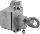 | 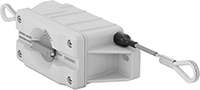 |
1 Direction | 2 Directions |
Connect these switches to a cable to control circuits from a distance. They're typically used to turn off production lines and material handling systems. Mount in any position and tug on the cable to send a switching signal. Equipment will not start up again until the switch is manually reset.
No. of Circuits Controlled | Switch Starting Position | Switch Action | No. of Terminals | Switch Designation | Switching Current @ Voltage | Max. Voltage | Actuation Force, lbf | Conduit Trade Size | Mounting Fasteners Included | Each | |||
|---|---|---|---|---|---|---|---|---|---|---|---|---|---|
Screw-Terminal Wire Connection | |||||||||||||
1 Direction (NEMA 1) | |||||||||||||
| 1 | 1 On | Maintained | 2 | SPST-NC | 6 amp @ 120V AC, 3 amp @ 240V AC, 0.6 amp @ 125V DC | 600V AC 600V DC | 2 to 6 | 1/2 | Yes | 7186K53 | 0000000 | ||
2 Directions (IP66, NEMA 4X) | |||||||||||||
| 1 | 1 Off or 1 On | Maintained | 3 | SPDT | 5 amp @ 125V AC, 1 amp @ 24V DC | 60V DC 250V AC | 0.2 to 2 | 1/2 | No | 7186K101 | 000000 | ||
Light Socket Pull Cords
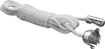 |
Overall Lg. | Each | ||
|---|---|---|---|
| 36" | 14695K65 | 00000 |
Hazardous Location Cable-Pull-Actuator Emergency Stop Switches
 |
Safe to use near ignitable gases and dust, the housing on these switches seals in anything that could ignite flammable material. All are UL listed and CSA certified for use in hazardous locations. Yank the cable anywhere along your line to quickly cut power in emergencies. They have positive-force, snap-open contacts that open a circuit when actuated, even if a spring fails or the contacts stick. The contacts will remain open until you tension the cable and reset the switch. Use the tension indicator to visually confirm that they’re reset correctly.
Mounting | ||||||||||||||||
|---|---|---|---|---|---|---|---|---|---|---|---|---|---|---|---|---|
For Max. Cable Lg., ft. | No. of Circuits Controlled | Switch Starting Position | No. of Terminals | Switch Designation | Switching Current @ Voltage | Max. Voltage | Actuation Force, lbf | Conduit Trade Size | Fasteners Included | Hole Dia. (No. of Holes) | Hole Thread Size (No. of Holes) | Features | Each | |||
Screw-Terminal Wire Connection | ||||||||||||||||
1 Direction (NEMA 4; NEMA 7; NEMA 9; NEMA 13; NEC Class I Divisions 1, 2 Groups B, C, D; NEC Class II Divisions 1, 2 Groups E, F, G) | ||||||||||||||||
| 200 | 1 | 1 Off or 1 On | 3 | SPDT | 10 amp @ 600V AC 10 amp @ 250V DC | 600V AC 250V DC | 25 | 1/2 | No | 1/4" (2) | 5/16"-18 (2) | Tension Indicator | 7543N11 | 000000000 | ||
| 200 | 2 | 2 On | 4 | DPST-NC | 10 amp @ 600V AC 10 amp @ 250V DC | 600V AC 250V DC | 25 | 1/2 | No | 1/4" (2) | 5/16"-18 (2) | Tension Indicator | 7543N12 | 00000000 | ||
Cable-Pull-Actuator Emergency Stop Switches with Restart Switch
1 Direction
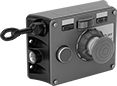 | 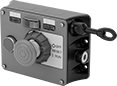 |
Left Side Cable Location | Right Side Cable Location |
Mounting | |||||||||||||||||
|---|---|---|---|---|---|---|---|---|---|---|---|---|---|---|---|---|---|
Cable Location | For Max. Cable Lg., ft. | No. of Circuits Controlled | Switch Starting Position | No. of Terminals | Switch Designation | Switching Current @ Voltage | Max. Voltage | Actuation Force, lbf | Conduit Trade Size | Bulb Voltage | Fasteners Included | No. of Holes | Hole Dia. | Each | |||
Screw-Terminal Wire Connection | |||||||||||||||||
With Emergency Stop Button, Power Indicator, Restart Button, Tension Indicator (IP54, NEMA 1) | |||||||||||||||||
| Left Side | 325 | 2 | 2 Off or 2 On | 6 | DPDT | 6 amp @ 120V AC 2.8 amp @ 24V DC | 240V AC 24V DC | 11 | 1/2 | 24V DC | No | 4 | 1/4" | 5746N301 | 000000000 | ||
| Left Side | 325 | 2 | 2 Off or 2 On | 6 | DPDT | 6 amp @ 120V AC 2.8 amp @ 24V DC | 240V AC 24V DC | 11 | 1/2 | 120V AC | No | 4 | 1/4" | 5746N201 | 00000000 | ||
| Right Side | 325 | 2 | 2 Off or 2 On | 6 | DPDT | 6 amp @ 120V AC 2.8 amp @ 24V DC | 240V AC 24V DC | 11 | 1/2 | 24V DC | No | 4 | 1/4" | 5746N11 | 00000000 | ||
| Right Side | 325 | 2 | 2 Off or 2 On | 6 | DPDT | 6 amp @ 120V AC 2.8 amp @ 24V DC | 240V AC 24V DC | 11 | 1/2 | 120V AC | No | 4 | 1/4" | 5746N202 | 00000000 | ||
2 Directions
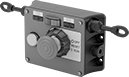 |
Two-direction switches support twice the total cable distance of one-direction switches. With pulls on each side, you can route cable in two opposite directions. These switches are often placed at the midpoint of conveyors and other long runs of equipment.
Mounting | |||||||||||||||||
|---|---|---|---|---|---|---|---|---|---|---|---|---|---|---|---|---|---|
Cable Location | For Max. Cable Lg., ft. | No. of Circuits Controlled | Switch Starting Position | No. of Terminals | Switch Designation | Switching Current @ Voltage | Max. Voltage | Actuation Force, lbf | Conduit Trade Size | Bulb Voltage | Fasteners Included | No. of Holes | Hole Dia. | Each | |||
Screw-Terminal Wire Connection | |||||||||||||||||
With Emergency Stop Button, Power Indicator, Restart Button, Tension Indicator (IP54, NEMA 1) | |||||||||||||||||
| Left Side, Right Side | 325 | 2 | 2 Off or 2 On | 6 | DPDT | 6 amp @ 120V AC 2.8 amp @ 24V DC | 240V AC 24V DC | 11 | 1/2 | 24V DC | No | 4 | 1/4" | 5746N12 | 000000000 | ||
| Left Side, Right Side | 325 | 2 | 2 Off or 2 On | 6 | DPDT | 6 amp @ 120V AC 2.8 amp @ 24V DC | 240V AC 24V DC | 11 | 1/2 | 120V AC | No | 4 | 1/4" | 5746N204 | 00000000 | ||
Plug-In Ceiling Lights
 |
Style C |
 |
Style D |
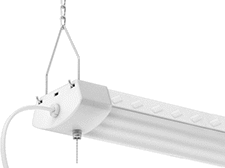
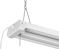
No need for wiring—these lights plug into a standard wall outlet. Also known as shop lights, they suspend from your ceiling or can be surface mounted with the included hardware. Their smooth, frosted lens disperses light and reduces glare. Since the lens is polycarbonate, these lights stand up to bumps. ETL listed for use in damp locations, they also withstand humidity and moisture.
Style C—Styles B-D can be chained together by plugging their power cord into the power outlet on the previous light. Style C are the brightest plug-in ceiling light, so they’re ideal for large areas.
Style D—Styles B-D can be chained together by plugging their power cord into the power outlet on the previous light.
Neutral Light—Neutral lights are often found in workspaces.
Cool Light—Cool lights highlight white and blue tones. This is ideal for inspection areas, workshops, and other areas that require high visibility.
Overall | |||||||||||||||||
|---|---|---|---|---|---|---|---|---|---|---|---|---|---|---|---|---|---|
Style | Lg. | Wd. | Ht. | Brightness, lm | Light Appearance (Color Temp.) | Wattage, W | Voltage | Switch Type | Housing Material | Outlet Included | Max. No. of Lights per Circuit | Mounting Hardware Included | Certification | Each | |||
LED | |||||||||||||||||
Plug In | |||||||||||||||||
| C | 47 1/4" | 4 1/2" | 2" | 12,000 | Cool (5,000 K) | 120 | 120V AC | Pull Chain | Aluminum | Yes | 3 | Yes | C-ETL Listed ETL Listed UL Listed | 1602K108 | 000000 | ||
| D | 48" | 5 1/4" | 2" | 4,500 | Neutral (4,000 K) | 45 | 120V AC | Pull Chain | Aluminum | Yes | 4 | Yes | C-ETL Listed ETL Listed | 1602K6 | 00000 | ||
Light Bulb Sockets
 | 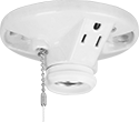 |
Style B | Style C |
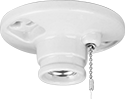
Install sockets for medium (standard household) screw-in base light bulbs. Made of porcelain, these sockets withstand high temperatures near bulbs without melting or deforming, making them suitable for enclosed fixtures. All are UL Listed.
Styles B and C—Styles A-C mount to outlet boxes.
Housing | Mounting Holes | ||||||||||||||||||
|---|---|---|---|---|---|---|---|---|---|---|---|---|---|---|---|---|---|---|---|
Style | Switch Type | Mount Type | Wire Connection | Overall Dia. | Voltage, V AC | Screw-In Base Size | Max. Wattage per Bulb, W | Collar Dia. | Material | Color | For Outlet Box Ht. | Mounting Hardware Included | No. of | Dia. | Certification | Each | |||
For LED, CFL, Halogen, and Incandescent Lights | |||||||||||||||||||
| B | Pull Chain | Fastener | Screw Terminal | 4 1/2" | 120, 208, 240 | Medium (Standard Household) | 250 | 1 11/16" | Porcelain | White | 3 1/4", 4" | Yes | 2 | 7/32" | UL Listed, CSA Certified | 16895K8 | 000000 | ||
| C | Pull Chain | Fastener | Screw Terminal | 4 1/2" | 120 | Medium (Standard Household) | 250 | 1 5/8" | Porcelain | White | 3 1/4", 4" | Yes | 2 | 7/32" | UL Listed, CSA Certified | 16895K9 | 00000 | ||
