Filter by
Actuator Style


Wire Connection

Switch Action
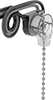
Pull Direction
Electrical Connection
Switch Type

Switch Starting Position
Export Control Classification Number (ECCN)
DFARS Specialty Metals
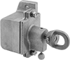
Housing Material
Electrical Power, Networking, and Controlling
Lighting
Safety Equipment