Filter by
For Use With
Valve Position
Thread Type
Maximum Pressure @ Temperature
Environment
Mounting Position
Flow Coefficient (Cv)
Valve Function


Wire Connection
Maximum Temperature
Fitting Connection

DFARS Specialty Metals
Air Directional Control Valve Flow Pattern
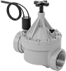
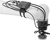
About Actuated On/Off Valves
Choose the right automatic on/off valve based on power source, pressure, and flow rate.
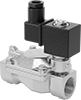
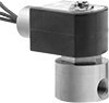
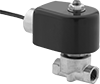
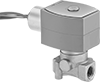
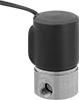
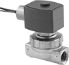
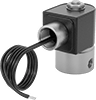
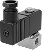
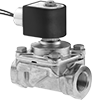
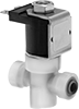
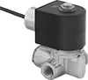
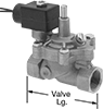
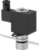
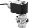
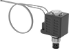
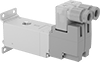
Solenoid On/Off Valves
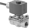
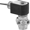
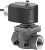
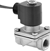
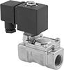
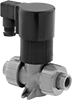
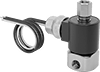
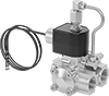
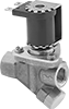
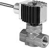
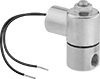
Solenoid On/Off Valves