



























Filter by
Environment
Pressure Set Point
For Use With
Thread Type
Fitting Connection

Housing Material
Hazardous Location Rating


Connection Material
Gasket Material

Maximum Temperature
Operates On
Approximate Difference Between Set Point and Reset Point
Wire Connection

Export Control Classification Number (ECCN)
DFARS Specialty Metals

About Pressure Switches
%20--%3e%3csvg%20version='1.1'%20id='Layer_1'%20xmlns='http://www.w3.org/2000/svg'%20xmlns:xlink='http://www.w3.org/1999/xlink'%20x='0px'%20y='0px'%20viewBox='0%200%20400%20400'%20style='enable-background:new%200%200%20400%20400;'%20xml:space='preserve'%3e%3cstyle%20type='text/css'%3e%20.st0{fill:%231A70A0;}%20.st1{opacity:0.5;}%20%3c/style%3e%3cg%3e%3cg%3e%3cpath%20class='st0'%20d='M200,56.9c38.35,0,74.4,14.93,101.51,42.05c27.11,27.11,42.05,63.17,42.05,101.51s-14.93,74.4-42.05,101.51%20S238.35,344.02,200,344.02s-74.4-14.93-101.51-42.05c-27.11-27.11-42.05-63.17-42.05-101.51s14.93-74.4,42.05-101.51%20S161.65,56.9,200,56.9%20M200,12.9C96.41,12.9,12.44,96.88,12.44,200.46c0,103.59,83.97,187.56,187.56,187.56%20c103.59,0,187.56-83.97,187.56-187.56C387.56,96.88,303.59,12.9,200,12.9L200,12.9z'/%3e%3c/g%3e%3cg%3e%3cg%20class='st1'%3e%3cpath%20class='st0'%20d='M235.49,152.24h16.15l-27.46,111.87c-1.94,7.8-2.91,12.5-2.91,14.1c0,1.82,0.58,3.29,1.73,4.41%20c1.16,1.12,2.69,1.68,4.61,1.68c5.23,0,11.78-3.85,19.63-11.55l17.22,21.34c-16.95,17.33-34.87,26-53.78,26%20c-8.37,0-15.45-1.47-21.23-4.41c-5.79-2.94-10.44-7.25-13.95-12.92c-3.51-5.67-5.27-11.18-5.27-16.53c0-1.93,0.35-5.24,1.05-9.94%20c1-6.94,2.05-12.54,3.15-16.82l15.22-62.15h-32.69l7.65-30.97C190.89,163.58,214.53,158.88,235.49,152.24z%20M230.44,80.84%20c8.24,0,14.66,2.62,19.26,7.86c4.6,5.24,6.9,11.55,6.9,18.94c0,5.46-1.42,10.7-4.25,15.73c-2.83,5.03-6.88,9.07-12.12,12.12%20c-5.24,3.05-10.33,4.57-15.24,4.57c-4.6,0-9.17-1.23-13.72-3.69c-4.55-2.46-8.02-5.78-10.43-9.95%20c-2.41-4.17-3.61-8.67-3.61-13.48c0-5.35,1.52-10.64,4.57-15.89c3.05-5.24,7.03-9.25,11.96-12.04%20C218.68,82.23,224.24,80.84,230.44,80.84z'/%3e%3c/g%3e%3cg%3e%3cpath%20class='st0'%20d='M214.08,152.24h16.15l-27.46,111.87c-1.94,7.8-2.91,12.5-2.91,14.1c0,1.82,0.58,3.29,1.73,4.41%20c1.16,1.12,2.69,1.68,4.61,1.68c5.23,0,11.78-3.85,19.63-11.55l17.22,21.34c-16.95,17.33-34.87,26-53.78,26%20c-8.37,0-15.45-1.47-21.23-4.41c-5.79-2.94-10.44-7.25-13.95-12.92c-3.51-5.67-5.27-11.18-5.27-16.53c0-1.93,0.35-5.24,1.05-9.94%20c1-6.94,2.05-12.54,3.15-16.82l15.22-62.15h-32.69l7.65-30.97C169.48,163.58,193.11,158.88,214.08,152.24z%20M209.03,80.84%20c8.24,0,14.66,2.62,19.26,7.86c4.6,5.24,6.9,11.55,6.9,18.94c0,5.46-1.42,10.7-4.25,15.73c-2.83,5.03-6.88,9.07-12.12,12.12%20c-5.24,3.05-10.33,4.57-15.24,4.57c-4.6,0-9.17-1.23-13.72-3.69c-4.55-2.46-8.02-5.78-10.43-9.95%20c-2.41-4.17-3.61-8.67-3.61-13.48c0-5.35,1.52-10.64,4.57-15.89c3.05-5.24,7.03-9.25,11.96-12.04%20C197.26,82.23,202.83,80.84,209.03,80.84z'/%3e%3c/g%3e%3c/g%3e%3c/g%3e%3c/svg%3e)
Compare different types of pressure switches and learn how they work.
Hazardous Location Pressure Switches
 |  |
Style A | Style B |
Built with an explosion-proof enclosure to meet NEMA 7 and 9 standards for hazardous locations, these switches were tested and verified by UL and CSA for use where explosive liquids, dust, and gas are present. When they reach the set pressure, they power equipment, signal controls, or trigger alarms. They’re single pole, double throw (SPDT) and can be installed to turn one circuit from off to on (normally open) or from on to off (normally closed). In addition to being UL listed and CSA certified, these switches are CE marked, so they also meet European safety standards.
All switches are IP and NEMA rated for use outdoors and protection from some corrosion, dust, and spraying water.
Wire Lead Connection
| |
Style A | Style B |
IP67 Enclosure Rating and NEMA 4X Enclosure Rating—IP67 and NEMA 4X rated switches seal out water from temporary submersion and have increased protection against corrosion, similar to 304 stainless steel.
Style | Pressure Set Point Range, psi | Approx. Difference Between Set Point and Reset Point, psi | Max. Continuous Pressure, psi | Max. Short-Term Pressure, psi | Accuracy | Max. Switching Current @ Voltage | Process Temp. Range, ° F | Connection Material | For Use With | Enclosure Rating | Hazardous Location Rating | Certification | Each | |||
|---|---|---|---|---|---|---|---|---|---|---|---|---|---|---|---|---|
1/4 Threaded NPT Male Pipe | ||||||||||||||||
Internal Adjustment | ||||||||||||||||
| A | 8 to 60 | 5 | 60 | 1,000 | ±5% | 5 amp @ 125V AC 5 amp @ 250V AC | -40 to 190 | 316 Stainless Steel | Air, Diesel Fuel, Gasoline, Hydraulic Fluid, Natural Gas, Water | IP67, NEMA 4X, NEMA 7, NEMA 9 | NEC Class I Divisions 1, 2 Groups A, B, C, D NEC Class II Divisions 1, 2 Groups E, F, G | CE Marked, CSA Certified, UL Listed | 46985K71 | 0000000 | ||
| A | 10 to 100 | 9 | 100 | 1,000 | ±5% | 5 amp @ 125V AC 5 amp @ 250V AC | -40 to 190 | 316 Stainless Steel | Air, Diesel Fuel, Gasoline, Hydraulic Fluid, Natural Gas, Water | IP67, NEMA 4X, NEMA 7, NEMA 9 | NEC Class I Divisions 1, 2 Groups A, B, C, D NEC Class II Divisions 1, 2 Groups E, F, G | CE Marked, CSA Certified, UL Listed | 46985K72 | 000000 | ||
| A | 20 to 200 | 16 | 200 | 1,000 | ±2% | 5 amp @ 125V AC 5 amp @ 250V AC | -40 to 190 | 316 Stainless Steel | Air, Diesel Fuel, Gasoline, Hydraulic Fluid, Natural Gas, Water | IP67, NEMA 4X, NEMA 7, NEMA 9 | NEC Class I Divisions 1, 2 Groups A, B, C, D NEC Class II Divisions 1, 2 Groups E, F, G | CE Marked, CSA Certified, UL Listed | 46985K73 | 000000 | ||
| A | 50 to 500 | 60 | 500 | 5,000 | ±2% | 5 amp @ 125V AC 5 amp @ 250V AC | -40 to 190 | 316 Stainless Steel | Air, Diesel Fuel, Gasoline, Hydraulic Fluid, Natural Gas, Water | IP67, NEMA 4X, NEMA 7, NEMA 9 | NEC Class I Divisions 1, 2 Groups A, B, C, D NEC Class II Divisions 1, 2 Groups E, F, G | CE Marked, CSA Certified, UL Listed | 46985K74 | 000000 | ||
| A | 100 to 1,000 | 87 | 1,000 | 5,000 | ±2% | 5 amp @ 125V AC 5 amp @ 250V AC | -40 to 190 | 316 Stainless Steel | Air, Diesel Fuel, Gasoline, Hydraulic Fluid, Natural Gas, Water | IP67, NEMA 4X, NEMA 7, NEMA 9 | NEC Class I Divisions 1, 2 Groups A, B, C, D NEC Class II Divisions 1, 2 Groups E, F, G | CE Marked, CSA Certified, UL Listed | 46985K75 | 000000 | ||
| A | 200 to 2,000 | 165 | 2,000 | 5,000 | ±2% | 5 amp @ 125V AC 5 amp @ 250V AC | -40 to 190 | 316 Stainless Steel | Air, Diesel Fuel, Gasoline, Hydraulic Fluid, Natural Gas, Water | IP67, NEMA 4X, NEMA 7, NEMA 9 | NEC Class I Divisions 1, 2 Groups A, B, C, D NEC Class II Divisions 1, 2 Groups E, F, G | CE Marked, CSA Certified, UL Listed | 46985K76 | 000000 | ||
1/2 Threaded NPT Female Pipe | ||||||||||||||||
Internal Adjustment | ||||||||||||||||
| B | 6 to 30 | 2 | 30 | 1,000 | ±1% | 5 amp @ 125V AC 5 amp @ 250V AC | 0 to 200 | 316 Stainless Steel | Air, Diesel Fuel, Gasoline, Hydraulic Fluid, Natural Gas, Water | IP66, NEMA 4, NEMA 7, NEMA 9 | NEC Class I Divisions 1, 2 Groups A, B, C, D NEC Class II Divisions 1, 2 Groups E, F, G | CE Marked, CSA Certified, UL Listed | 46985K61 | 000000 | ||
| B | 12 to 60 | 2 | 60 | 1,000 | ±1% | 5 amp @ 125V AC 5 amp @ 250V AC | 0 to 200 | 316 Stainless Steel | Air, Diesel Fuel, Gasoline, Hydraulic Fluid, Natural Gas, Water | IP66, NEMA 4, NEMA 7, NEMA 9 | NEC Class I Divisions 1, 2 Groups A, B, C, D NEC Class II Divisions 1, 2 Groups E, F, G | CE Marked, CSA Certified, UL Listed | 46985K62 | 000000 | ||
| B | 20 to 100 | 3.5 | 100 | 1,000 | ±1% | 5 amp @ 125V AC 5 amp @ 250V AC | 0 to 200 | 316 Stainless Steel | Air, Diesel Fuel, Gasoline, Hydraulic Fluid, Natural Gas, Water | IP66, NEMA 4, NEMA 7, NEMA 9 | NEC Class I Divisions 1, 2 Groups A, B, C, D NEC Class II Divisions 1, 2 Groups E, F, G | CE Marked, CSA Certified, UL Listed | 46985K63 | 000000 | ||
| B | 40 to 200 | 6.5 | 200 | 1,000 | ±1% | 5 amp @ 125V AC 5 amp @ 250V AC | 0 to 200 | 316 Stainless Steel | Air, Diesel Fuel, Gasoline, Hydraulic Fluid, Natural Gas, Water | IP66, NEMA 4, NEMA 7, NEMA 9 | NEC Class I Divisions 1, 2 Groups A, B, C, D NEC Class II Divisions 1, 2 Groups E, F, G | CE Marked, CSA Certified, UL Listed | 46985K64 | 000000 | ||
| B | 80 to 400 | 11 | 400 | 1,600 | ±1% | 5 amp @ 125V AC 5 amp @ 250V AC | 0 to 200 | 316 Stainless Steel | Air, Diesel Fuel, Gasoline, Hydraulic Fluid, Natural Gas, Water | IP66, NEMA 4, NEMA 7, NEMA 9 | NEC Class I Divisions 1, 2 Groups A, B, C, D NEC Class II Divisions 1, 2 Groups E, F, G | CE Marked, CSA Certified, UL Listed | 46985K65 | 000000 | ||
Hazardous Location Rotatable DC Metallic-Object Proximity Sensors
 |
 |  |
4-Pole M12 Plug | Flush Mount |
 | |
Projecting Mount |
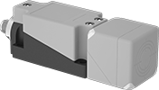
Twist the sensor to detect metallic objects where explosive dust or gas may be present—the sensor rotates for front, side, top, or bottom sensing. These sensors are UL and C-UL listed as well as ATEX and IECEx certified for hazardous locations. Their NAMUR signal produces low current and low voltage, so they won’t spark or ignite. You must connect them to a barrier (sold separately), which reduces the current and voltage that enters your hazardous area.
Because you can rotate the sensor, these make good replacements for limit switches with actuators that could break when hit. They’re often known as inductive proximity sensors and detect objects even if they’re covered by water, oil, dirt, or a surface finish. Sensing distance is based on the type of material that’s sensed; the distance listed is for mild steel. Send signals from these sensors to programmable logic controllers (PLCs) to support automated processes.
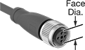
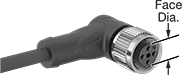
These sensors have a 4-pole M12 plug that connects to cables with a socket (sold separately), so you can quickly connect and disconnect them. You can also check on them from any angle, thanks to LED status indicators on their corners. All are CE marked for safety.
To view wiring diagrams, select a part number and click Product Detail.
IP rated, all sensors seal out dust and water from high-pressure washdowns.
IP67 Enclosure Rating and IP68 Enclosure Rating—IP67- and IP68-rated sensors withstand some submersion.
Flush Mount—Flush sensors, also called embeddable and shielded sensors, are more accurate than projecting sensors at close range. They also won’t interfere with each other’s signals when installed close together. Their sensor face mounts evenly with any material, including metal.
Projecting Mount—Projecting sensors, also known as non-embeddable and unshielded sensors, sense objects farther away than flush sensors. But, the area around the sensor must be metal free.
Switch Starting Position | Max. Sensing Distance, mm | Output Digital Signal | Input Voltage | Current Output | Electrical Connection Type | Lg., mm | Wd., mm | Ht., mm | Circuit Protection | Features | Temp. Range, ° F | Hazardous Location Rating | Certification | Each | |||
|---|---|---|---|---|---|---|---|---|---|---|---|---|---|---|---|---|---|
Plastic Housing (IP66, IP69K) | |||||||||||||||||
Flush with 4-Pole M12 Plug Connection | |||||||||||||||||
| 1 On | 20 | NAMUR | 8V DC to 8.5V DC | 10 mA | Plug In | 67 | 40 | 40 | Reverse Polarity Short Circuit | LED Power Indicator, LED Status Indicator, Rotatable Sensor | -10 to 210 | ATEX II 1 D Ex Ia IIIC T135° C Da; ATEX II 1 G Ex Ia IIC T6...T1 Ga; ATEX II 2 G Ex Ia IIC T6...T1 Gb; IEC Zone 0 Groups IIC, IIB, IIA; IEC Zone 20 Groups IIIC, IIIB, IIIA; IECEx Ex Ia I Mb; IECEx Ex Ia IIC T6...T1 Ga; IECEx Ex Ia IIC T6...T1 Gb; IECEx Ex Ia IIIC T135° C Da; NEC Class I Divisions 1, 2 Groups A, B, C, D; NEC Class II Divisions 1, 2 Groups E, F, G; NEC Class III Divisions 1, 2 | C-UL Listed, CE Marked, UL Listed | 7104N12 | 0000000 | ||
Plastic Housing (IP67, IP69K) | |||||||||||||||||
Flush with 4-Pole M12 Plug Connection | |||||||||||||||||
| 1 On | 20 | NAMUR | 8V DC to 8.5V DC | 10 mA | Plug In | 118 | 40 | 40 | Reverse Polarity Short Circuit | LED Power Indicator, LED Status Indicator, Rotatable Sensor | -10 to 210 | ATEX II 1 D Ex Ia IIIC T135° C Da; ATEX II 1 G Ex Ia IIC T6...T1 Ga; ATEX II 2 G Ex Ia IIC T6...T1 Gb; IEC Zone 0 Groups IIC, IIB, IIA; IEC Zone 20 Groups IIIC, IIIB, IIIA; IECEx Ex Ia I Mb; IECEx Ex Ia IIC T6...T1 Ga; IECEx Ex Ia IIC T6...T1 Gb; IECEx Ex Ia IIIC T135° C Da; NEC Class I Divisions 1, 2 Groups A, B, C, D; NEC Class II Divisions 1, 2 Groups E, F, G; NEC Class III Divisions 1, 2 | C-UL Listed, CE Marked, UL Listed | 6305N111 | 000000 | ||
Plastic Housing (IP69K) | |||||||||||||||||
Projecting with 4-Pole M12 Plug Connection | |||||||||||||||||
| 1 On | 40 | NAMUR | 8V DC to 8.5V DC | 10 mA | Plug In | 67 | 40 | 40 | Reverse Polarity Short Circuit | LED Power Indicator, LED Status Indicator, Rotatable Sensor | -10 to 210 | ATEX II 1 D Ex Ia IIIC T135° C Da; ATEX II 1 G Ex Ia IIC T6...T1 Ga; ATEX II 2 G Ex Ia IIC T6...T1 Gb; IEC Zone 0 Groups IIC, IIB, IIA; IEC Zone 20 Groups IIIC, IIIB, IIIA; IECEx Ex Ia I Mb; IECEx Ex Ia IIC T6...T1 Ga; IECEx Ex Ia IIC T6...T1 Gb; IECEx Ex Ia IIIC T135° C Da; NEC Class I Divisions 1, 2 Groups A, B, C, D; NEC Class II Divisions 1, 2 Groups E, F, G; NEC Class III Divisions 1, 2 | C-UL Listed, CE Marked, UL Listed | 7104N13 | 000000 | ||
Plastic Housing (IP68, IP69K) | |||||||||||||||||
Projecting with 4-Pole M12 Plug Connection | |||||||||||||||||
| 1 On | 40 | NAMUR | 8V DC to 8.5V DC | 10 mA | Plug In | 118 | 40 | 40 | Reverse Polarity Short Circuit | LED Power Indicator, LED Status Indicator, Rotatable Sensor | -10 to 210 | ATEX II 1 D Ex Ia IIIC T135° C Da; ATEX II 1 G Ex Ia IIC T6...T1 Ga; ATEX II 2 G Ex Ia IIC T6...T1 Gb; IEC Zone 0 Groups IIC, IIB, IIA; IEC Zone 20 Groups IIIC, IIIB, IIIA; IECEx Ex Ia I Mb; IECEx Ex Ia IIC T6...T1 Ga; IECEx Ex Ia IIC T6...T1 Gb; IECEx Ex Ia IIIC T135° C Da; NEC Class I Divisions 1, 2 Groups A, B, C, D; NEC Class II Divisions 1, 2 Groups E, F, G; NEC Class III Divisions 1, 2 | C-UL Listed, CE Marked, UL Listed | 6305N112 | 000000 | ||
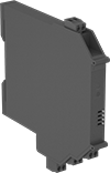 |
Install the barrier in a separate location that doesn’t contain explosive gas or dust.
Inputs | Outputs | ||||||||||||
|---|---|---|---|---|---|---|---|---|---|---|---|---|---|
Operating Voltage, V DC | Voltage, V DC | Current, mA | No. of | Signal | Current, amp | No. of | Switching Freq., kHz | Hazardous Location Rating | Enclosure Rating | Each | |||
Plastic Housing | |||||||||||||
| 24 | 10 | 8 | 1 | NAMUR | 0.05 | 2 | 5 | ATEX I (M1) [Ex Ia Ma] I; ATEX II (1)D [Ex Ia Da] IIIC; ATEX II (1)G [Ex Ia Ga] IIC; Associated Apparatus for IEC Zone 0 Groups IIC, IIB, IIA; Associated Apparatus for IEC Zone 20 Groups IIIC, IIIB, IIIA; IECEx [Ex Ia Da] IIIC; IECEx [Ex Ia Ga] IIC; IECEx [Ex Ia Ma] I; IECEx Ex Ec IIC T4 Gc | IP20 | 7107N12 | 0000000 | ||
Fixed-Set-Point Hazardous-Location Flow Switches
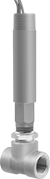 |
Safe to use where flammable gases and combustible dust may be present, these switches activate or deactivate when your flow reaches a factory-set level. All are UL listed for hazardous environments. Because their set point is fixed, they’re ready to go, making them easy to install. They actuate when your flowing liquid or gas pushes their paddle into a set position. These switches are single pole, double throw (SPDT) and can turn one device from off to on (normally open) or from on to off (normally closed). They must be mounted horizontally to function accurately.
These switches are calibrated with water and air. They can also be used with other liquids and gases but may not measure accurately if their viscosity is significantly different.
Set Point | Conduit | |||||||||||||||
|---|---|---|---|---|---|---|---|---|---|---|---|---|---|---|---|---|
Pipe Connections | For Liquids, gpm | For Gas, scfm | Max. Pressure @ Temp. | Temp. Range, ° F | Voltage, V AC | Max. Switching Current @ Voltage | Trade Size | Thread Type | Gender | End-to-End Lg. | Enclosure Rating | Certification | Each | |||
304 Stainless Steel Body with Threaded 304 Stainless Steel Fittings | ||||||||||||||||
| 1/2 NPT Female | 1.5 | 6.5 | 2,000 psi @ 70° F | -4 to 220 | 120/240 | 5 amp @ 120V AC | 3/4 | NPT | Male | 2 1/4" | NEMA 4 | UL Listed CE Marked | 47565K61 | 0000000 | ||
| 3/4 NPT Female | 2 | 10 | 2,000 psi @ 70° F | -4 to 220 | 120/240 | 5 amp @ 120V AC | 3/4 | NPT | Male | 2 5/8" | NEMA 4 | UL Listed CE Marked | 47565K62 | 000000 | ||
| 1 NPT Female | 3 | 14 | 2,000 psi @ 70° F | -4 to 220 | 120/240 | 5 amp @ 120V AC | 3/4 | NPT | Male | 3" | NEMA 4 | UL Listed CE Marked | 47565K63 | 000000 | ||
| 2 NPT Female | 10 | 43 | 2,000 psi @ 70° F | -4 to 220 | 120/240 | 5 amp @ 120V AC | 3/4 | NPT | Male | 4 3/4" | NEMA 4 | UL Listed CE Marked | 47565K66 | 00000000 | ||
Hazardous-Location Flow Switches
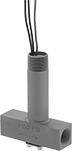 |
UL listed for use where flammable gases or combustible dusts may be present, these flow switches activate or deactivate equipment when your flow rate reaches a set point. Use the adjustment screw to select their set point. They actuate when your flowing liquid or gas pushes their paddle into a certain position determined by the set point. All are single pole, double throw (SPDT) and can either turn one device from off to on (normally open) or on to off (normally closed). Mount them horizontally. Rated NEMA 4, they also protect against weather and washdowns.
These flow switches are calibrated with water and air. You can use them with other liquids and gases, but they may not measure accurately if the viscosity is different from water or air.
Flow Set Point | Conduit | |||||||||||||||
|---|---|---|---|---|---|---|---|---|---|---|---|---|---|---|---|---|
Pipe Connections | For Liquids, gpm | For Gas, scfm | Max. Pressure @ Temp. | Temp. Range, ° F | Voltage, V AC | Max. Switching Current @ Voltage | Trade Size | Thread Type | Gender | End-to-End Lg. | Enclosure Rating | Certification | Each | |||
304 Stainless Steel Body with Threaded 304 Stainless Steel Fittings | ||||||||||||||||
| 1/2 NPT Female | 0.04 to 0.75 | 0.18 to 2.7 | 1,450 psi @ 70° F | -4 to 220 | 120/240 | 5 amp @ 120V AC | 3/4 | NPT | Male | 3 5/8" | NEMA 4 | UL Listed CE Marked | 91445K24 | 0000000 | ||
Hazardous Location Float Switches for Chemicals
 |  |
Style A |
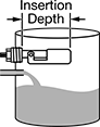
Designed for use in areas where flammable substances are present, these switches are CSA certified for hazardous locations. Mount them through a tank wall.
Style A—Style A meet Class I, Divisions 1 and 2, Groups A, B, C, and D; Class II, Divisions 1 and 2, Groups E, F, and G; and Class III, Divisions 1 and 2.
Pipe | Conduit | ||||||||||||||||||
|---|---|---|---|---|---|---|---|---|---|---|---|---|---|---|---|---|---|---|---|
Style | Size | Thread Type | Gender | Min. Specific Gravity | Max. Pressure @ Temp. | Temp. Range, ° F | Insertion Dp. | Switch Starting Position | Switch Designation | Current @ Voltage | Electrical Connection | Trade Size | Thread Type | Gender | Certification | Each | |||
120V AC/240V AC Input Voltage | |||||||||||||||||||
316 Stainless Steel Body and Float | |||||||||||||||||||
| A | 1/2 | NPT | Male | 0.7 | 300 psi @ 70° F | 0 to 390 | 4 5/8" | 1 Off/1 On | SPST-NO SPST-NC | 0.28 amp @ 120V AC | Wire Leads | 1/4 | NPT | Male | UL Recognized Component, CSA Certified, CE Marked | 46815K11 | 0000000 | ||
| A | 1/2 | NPT | Male | 0.7 | 300 psi @ 70° F | 0 to 390 | 4 5/8" | 1 Off/1 On | SPST-NO SPST-NC | 0.28 amp @ 120V AC | Wire Leads | 1/2 | NPT | Male | UL Recognized Component, CSA Certified, CE Marked | 46815K22 | 000000 | ||
| A | 1 | NPT | Male | 0.7 | 300 psi @ 70° F | 0 to 390 | 4 5/8" | 1 Off/1 On | SPST-NO SPST-NC | 0.28 amp @ 120V AC | Wire Leads | 1/2 | NPT | Male | UL Recognized Component, CSA Certified, CE Marked | 46815K21 | 000000 | ||
Horizontal-Mount Hazardous Location Float Switches for Fuels and Oils
 |  |
Style A | Style B |
|
Designed for use in areas where flammable substances are present, these switches are CSA certified for hazardous locations. Mount them through a tank wall. All are rated NEMA 4 for protection from washdowns. All are single pole, double throw (SPDT) and can be installed to turn one circuit from “off” to “on” or from “on” to “off”.
Switches with a stainless steel body are more corrosion resistant than switches with a brass body.
Pipe | Conduit | |||||||||||||||||
|---|---|---|---|---|---|---|---|---|---|---|---|---|---|---|---|---|---|---|
Style | Size | Thread Type | Gender | Min. Specific Gravity | Max. Pressure @ Temp. | Temp. Range, ° F | Insertion Dp. | Current @ Voltage | Float Material | Trade Size | Thread Type | Gender | Hazardous Location Rating | Enclosure Rating | Each | |||
120V AC/240V AC Input Voltage | ||||||||||||||||||
303 Stainless Steel Body | ||||||||||||||||||
| A | 1 | NPT | Male | 0.9 | 2,000 psi @ 70° F | 0 to 220 | 1 3/4" | 5 amp @ 120V AC | Polypropylene | 3/4 | NPT | Male | NEC Class I Divisions 1, 2 Groups A, B, C, D NEC Class II Divisions 1, 2 Groups E, F, G | NEMA 4 | 4909K65 | 0000000 | ||
| B | 1 | NPT | Male | 0.5 | 200 psi @ 70° F | 0 to 220 | 2 7/8" | 5 amp @ 120V AC | 304 Stainless Steel | 3/4 | NPT | Male | NEC Class I Divisions 1, 2 Groups A, B, C, D NEC Class II Divisions 1, 2 Groups E, F, G | NEMA 4 | 4909K13 | 000000 | ||
Hazardous Location Electrically Operated Air Directional Control Valves
Threaded Female Inlet × Threaded Female Outlet—Threaded Exhaust
 | 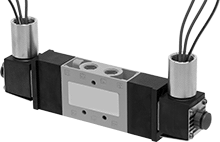 |
Single Solenoid | Double Solenoid |
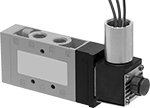
5/3 (Closed Center) Flow Pattern—5/3 (closed center) valves close all ports in the off position to stop equipment in a locked position with air pressure holding it in place.
Flow Coefficient (Cv)—Flow coefficient (Cv) indicates how much airflow can pass through a valve.
Hazardous Location Rating—Hazardous location ratings indicate whether manufacturers have included safety features in products to facilitate their safe use in a hazardous environment. Before selecting a product for a hazardous location, ensure it is rated for your environment.
Overall | ||||||||||||||||||
|---|---|---|---|---|---|---|---|---|---|---|---|---|---|---|---|---|---|---|
No. of Flow Ports | Inlet Size | Outlet Size | Max. Flow Rate @ 100 psi, scfm | Flow Coefficient (Cv) | Pressure Range, psi | Vacuum Rating, in. Hg | Hazardous Location Rating | Enclosure Rating | Voltage | Wire Connection | Lg. | Wd. | Ht. | Mounting Fasteners Included | Each | |||
5/2 Flow Pattern | ||||||||||||||||||
Single Solenoid | ||||||||||||||||||
| 5 | 1/4 NPT | 1/4 NPT | 65.34 | 1.7 | 14 to 145 | 28 | NEC Class I Divisions 1, 2 Groups A, B, C, D NEC Class II Divisions 1, 2 Groups E, F, G | NEMA 3S NEMA 6P NEMA 7 NEMA 9 | 24V DC | Wire Leads | 6" | 1" | 2 7/8" | No | 2992N11 | 0000000 | ||
| 5 | 1/4 NPT | 1/4 NPT | 65.34 | 1.7 | 14 to 145 | 28 | NEC Class I Divisions 1, 2 Groups A, B, C, D NEC Class II Divisions 1, 2 Groups E, F, G | NEMA 3S NEMA 6P NEMA 7 NEMA 9 | 120V AC | Wire Leads | 6" | 1" | 2 7/8" | No | 2992N12 | 000000 | ||
5/3 (Closed Center) Flow Pattern | ||||||||||||||||||
Double Solenoid | ||||||||||||||||||
| 5 | 1/4 NPT | 1/4 NPT | 65.34 | 1.7 | 14 to 145 | 28 | NEC Class I Divisions 1, 2 Groups A, B, C, D NEC Class II Divisions 1, 2 Groups E, F, G | NEMA 3S NEMA 6P NEMA 7 NEMA 9 | 24V DC | Wire Leads | 9 3/8" | 1" | 2 7/8" | No | 2992N13 | 000000 | ||
| 5 | 1/4 NPT | 1/4 NPT | 65.34 | 1.7 | 14 to 145 | 28 | NEC Class I Divisions 1, 2 Groups A, B, C, D NEC Class II Divisions 1, 2 Groups E, F, G | NEMA 3S NEMA 6P NEMA 7 NEMA 9 | 120V AC | Wire Leads | 9 3/8" | 1" | 2 7/8" | No | 2992N14 | 000000 | ||
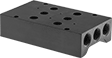 |
Manifolds are for single-solenoid, 24V DC valves.
No. of | Overall | |||||||||||||
|---|---|---|---|---|---|---|---|---|---|---|---|---|---|---|
Flow Ports | Inlet Ports | Exhaust Ports | Inlet Size | Exhaust Connection | Wd. | Ht. | Mount Type | Mounting Hole Dia. | Mounting Fasteners Included | Choose a Number of Stations | Each | |||
Manifold Style 4 | ||||||||||||||
| 6 | 2 | 4 | 3/8 NPTF | Threaded | 2 3/4" | 1 1/2" | Screw In | 0.16" | No | 2, 3, 4 | 6425K41 | 0000000 | ||
| 6 | 2 | 4 | 3/8 NPTF | Threaded | 2 3/4" | 1 1/2" | Screw In | 0.16" | No | 5, 6, 8 | 6425K42 | 000000 | ||
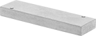 |
For Manifold Style | Body Material | Each | ||
|---|---|---|---|---|
| 4 | Aluminum | 6425K437 | 000000 |
