



























Filter by
Actuator Style


Switch Action

Switching Current
Number of Buttons
Switch Starting Position
Wire Connection


Housing Material
Electrical Connection


Number of Pedals

Export Control Classification Number (ECCN)
DFARS Specialty Metals
Pendant Switches
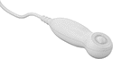 | 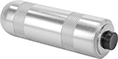 |
Wire Lead Connection Ergonomic Design | Tab Wire Connection |
Control machinery from a safe distance, or use these switches as call buttons.
Ergonomic Design—Ergonomic switches contour to fit naturally in your hand for comfort.
Wire Leads | ||||||||||||||||
|---|---|---|---|---|---|---|---|---|---|---|---|---|---|---|---|---|
No. of Buttons | No. of Circuits Controlled per Actuator | Switch Starting Position | Switch Action | No. of Terminals per Actuator | Switch Designation | Switching Current @ Voltage | Max. Voltage | Housing Material | No. of | AWG | Lg., ft. | Features | Each | |||
1 Speed with Wire Leads | ||||||||||||||||
| 1 | 2 | 2 Off | Momentary | 4 | DPDT-NO | 0.25 amp @ 36V AC 0.25 amp @ 20V DC | 120V AC 48V DC | Gray Plastic | 4 | 26 | 6 | Ergonomic Design, Strain Relief | 6944K103 | 000000 | ||
1 Speed with Tab Terminals | ||||||||||||||||
| 1 | 1 | 1 Off or 1 On | Momentary | 3 | SPDT | 0.25 amp @ 125V AC 0.25 amp @ 48V DC | 125V AC 48V DC | Copper | — | — | — | — | 6944K101 | 00000 | ||
| 1 | 1 | 1 Off or 1 On | Momentary | 3 | SPDT | 0.25 amp @ 125V AC 0.25 amp @ 48V DC | 125V AC 48V DC | Zinc Alloy | — | — | — | Strain Relief | 6944K102 | 00000 | ||
Wet-Location Foot Switches
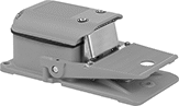 | 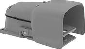 |
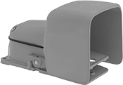
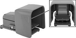
Switch | Switch with Guard |
 |  |
Switch with Oversized Guard | Switch with Safety Lever and Oversized Guard |
Operate these switches hands-free when working in wet or humid environments. They’re IP and NEMA rated, so they won’t corrode when exposed to water, oil, or coolant spray.
Oversized Guard—Switches with an oversized guard fit bulky shoes and toe guards.
Safety Lever—Switches with a safety lever lock the pedal in place to prevent accidental activation. Fully insert your foot to release the safety lever. If the lever isn't released, the pedal won't depress.
With Guard—Switches with a guard shield the pedal so you don't accidentally step on it and activate the switch.
Without Guard—Switches without a guard are unobstructed and let you press them from multiple angles.
2 Speeds—Two-speed switches have two contact points. Push the pedal halfway down for the slow speed or all the way down for the high speed.
Number of | Mounting | ||||||||||||||
|---|---|---|---|---|---|---|---|---|---|---|---|---|---|---|---|
Speeds | Circuits Controlled | Switch Starting Position | Switch Action | Switch Designation | Switching Current @ Voltage | Wire Connection | No. of Terminals | Conduit Trade Size | Fasteners Included | No. of Holes | Hole Dia. | Each | |||
Iron Housing | |||||||||||||||
IP56, NEMA 4, NEMA 13 | |||||||||||||||
| 1 | 1 | 1 Off or 1 On | Momentary | SPDT | 20 amp @ 125V AC, 250V AC, 0.5 amp @ 125V DC, 0.25 amp @ 250V DC | Screw Terminal | 3 | 3/4 | No | 3 | 0.31" | 7372K101 | 0000000 | ||
| 1 | 1 | 1 Off or 1 On | Maintained | SPDT | 20 amp @ 125V AC, 250V AC, 0.5 amp @ 125V DC, 0.25 amp @ 250V DC | Screw Terminal | 3 | 3/4 | No | 3 | 0.31" | 7372K102 | 000000 | ||
| 1 | 2 | 2 Off or 2 On | Momentary | DPDT | 20 amp @ 125V AC, 250V AC, 0.5 amp @ 125V DC, 0.25 amp @ 250V DC | Screw Terminal | 6 | 3/4 | No | 3 | 0.31" | 7372K103 | 000000 | ||
| 2 | 1 | 1 Off or 1 On | Momentary | SPDT | 20 amp @ 125V AC, 250V AC, 0.5 amp @ 125V DC, 0.25 amp @ 250V DC | Screw Terminal | 6 | 3/4 | No | 3 | 0.31" | 7372K104 | 000000 | ||
Iron Housing with Aluminum Guard | |||||||||||||||
IP56, NEMA 4, NEMA 13 | |||||||||||||||
| 1 | 1 | 1 Off or 1 On | Momentary | SPDT | 20 amp @ 125V AC, 250V AC, 0.5 amp @ 125V DC, 0.25 amp @ 250V DC | Screw Terminal | 3 | 3/4 | No | 3 | 0.31" | 7372K11 | 000000 | ||
| 1 | 1 | 1 Off or 1 On | Maintained | SPDT | 20 amp @ 125V AC, 250V AC, 0.5 amp @ 125V DC, 0.25 amp @ 250V DC | Screw Terminal | 3 | 3/4 | No | 3 | 0.31" | 7372K14 | 000000 | ||
| 1 | 2 | 2 Off or 2 On | Momentary | DPDT | 20 amp @ 125V AC, 250V AC, 0.5 amp @ 125V DC, 0.25 amp @ 250V DC | Screw Terminal | 6 | 3/4 | No | 3 | 0.31" | 7372K12 | 000000 | ||
| 2 | 1 | 1 Off or 1 On | Momentary | SPDT | 20 amp @ 125V AC, 250V AC, 0.5 amp @ 125V DC, 0.25 amp @ 250V DC | Screw Terminal | 6 | 3/4 | No | 3 | 0.31" | 7372K51 | 000000 | ||
Iron Housing with Oversized Aluminum Guard | |||||||||||||||
IP56, NEMA 4, NEMA 13 | |||||||||||||||
| 1 | 1 | 1 Off or 1 On | Momentary | SPDT | 20 amp @ 125V AC, 250V AC, 0.5 amp @ 125V DC, 0.25 amp @ 250V DC | Screw Terminal | 3 | 3/4 | No | 3 | 0.31" | 7372K31 | 000000 | ||
| 1 | 1 | 1 Off or 1 On | Maintained | SPDT | 20 amp @ 125V AC, 250V AC, 0.5 amp @ 125V DC, 0.25 amp @ 250V DC | Screw Terminal | 3 | 3/4 | No | 3 | 0.31" | 7372K32 | 000000 | ||
| 1 | 2 | 2 Off or 2 On | Momentary | DPDT | 20 amp @ 125V AC, 250V AC, 0.5 amp @ 125V DC, 0.25 amp @ 250V DC | Screw Terminal | 6 | 3/4 | No | 3 | 0.31" | 7372K34 | 000000 | ||
| 2 | 1 | 1 Off or 1 On | Momentary | SPDT | 20 amp @ 125V AC, 250V AC, 0.5 amp @ 125V DC, 0.25 amp @ 250V DC | Screw Terminal | 6 | 3/4 | No | 3 | 0.31" | 7372K71 | 000000 | ||
Iron Housing with Safety Lever and Oversized Aluminum Guard | |||||||||||||||
IP56, NEMA 4, NEMA 13 | |||||||||||||||
| 1 | 1 | 1 Off or 1 On | Momentary | SPDT | 20 amp @ 125V AC, 250V AC, 0.5 amp @ 125V DC, 0.25 amp @ 250V DC | Screw Terminal | 3 | 3/4 | No | 3 | 0.31" | 7344K31 | 000000 | ||
| 1 | 2 | 2 Off or 2 On | Momentary | DPDT | 20 amp @ 125V AC, 250V AC, 0.5 amp @ 125V DC, 0.25 amp @ 250V DC | Screw Terminal | 6 | 3/4 | No | 3 | 0.31" | 7344K32 | 000000 | ||
| 2 | 1 | 1 Off or 1 On | Momentary | SPDT | 20 amp @ 125V AC, 250V AC, 0.5 amp @ 125V DC, 0.25 amp @ 250V DC | Screw Terminal | 6 | 3/4 | No | 3 | 0.31" | 7372K105 | 000000 | ||
Tilt Switches
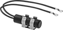 |
Style A |
Often used as position indicators, pump level controls, and machine limit switches, these switches actuate when tilted to a certain angle. They mount horizontally and activate when tilted downward, and deactivate when tilted up. All combine electromechanical and solid state technologies for reliability and long life.
Differential Angle—Differential angle is the total angle from the point of activation to the point of deactivation.
Style | No. of Circuits Controlled | Switch Starting Position | Switch Designation | Switching Current @ Voltage | Max. Voltage | Differential Angle | No. of Wire Leads | Dia. | Lg. | Housing Material | Enclosure Rating | Each | |||
|---|---|---|---|---|---|---|---|---|---|---|---|---|---|---|---|
Ring-Terminal Wire Connection | |||||||||||||||
| A | 1 | 1 Off | SPST-NO | 0.1 amp @ 120V AC, 0.25 amp @ 24V DC | 60V DC/120V AC | 15° | 2 | 0.53" | 1.88" | Plastic | NEMA 4, IP67 | 3108K1 | 000000 | ||
Miniature Panel-Mount Push-Button Switches
 |
4 mm |
Sized for 4 mm or 6 mm panel cutouts, these switches are often used with circuit boards to control electronics. They actuate with a quick push. Choose switches based on their actuator color for an easy way to tell them apart.
No. of Circuits Controlled | Switch Starting Position | Switch Action | No. of Terminals | Switch Designation | Switching Current @ Voltage | Max. Voltage | Dia. | Dp. Behind Panel | Actuator Color | Each | |||
|---|---|---|---|---|---|---|---|---|---|---|---|---|---|
Metal Actuator Base with Solder Connection | |||||||||||||
For 4 mm ( 5/32") Diameter Panel Cutouts | |||||||||||||
| 1 | 1 On | Momentary | 2 | SPST-NC | 0.25 amp @ 120V AC/28V DC | 120V AC 28V DC | 0.11" | 0.57" | Black | 7397K13 | 000000 | ||
Rotary Limit Switches
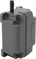 |
Start or stop equipment after a set number of rotations to avoid over-rotation. For example, if attached to a crane spool, these switches will stop winding or unwinding cable after a certain number of rotations, preventing damage to equipment. Use their shaft to attach them to rotational equipment. They open and close circuits as fast as snap-acting switches.
Gear Speed Ratio—Gear speed ratio determines when these switches actuate. A gear speed ratio of 5:1 means they actuate after 5 rotations.
Housing | Shaft | ||||||||||||||||||||
|---|---|---|---|---|---|---|---|---|---|---|---|---|---|---|---|---|---|---|---|---|---|
Gear Speed Ratio | No. of Circuits Controlled | Switch Starting Position | Switch Action | Switch Designation | Switching Current @ Voltage | Max. Voltage | Operating Temp. Range, ° F | No. of Terminals | Lg. | Ht. | Dp. | Housing Material | Type | Lg. | Dia. | Conduit Trade Size | Enclosure Rating | Each | |||
Rotary Actuator | |||||||||||||||||||||
Screw-Terminal Wire Connection | |||||||||||||||||||||
| 5:1 | 2 | 1 Off or 1 On | Momentary | SPDT | 15 amp @ 250V AC, 0.25 amp @ 250V DC | 480V AC 250V DC | -40 to 180 | 3 | 6" | 2.8" | 4.5" | Aluminum | Keyed | 1 1/2" | 1/2" | 1/2 | NEMA 4 | 7821N11 | 000000000 | ||
| 20:1 | 2 | 1 Off or 1 On | Momentary | SPDT | 15 amp @ 250V AC, 0.25 amp @ 250V DC | 480V AC 250V DC | -40 to 180 | 3 | 6" | 2.8" | 4.5" | Aluminum | Keyed | 1 1/2" | 1/2" | 1/2 | NEMA 4 | 7821N12 | 00000000 | ||
| 40:1 | 2 | 1 Off or 1 On | Momentary | SPDT | 15 amp @ 250V AC, 0.25 amp @ 250V DC | 480V AC 250V DC | -40 to 180 | 3 | 6" | 2.8" | 4.5" | Aluminum | Keyed | 1 1/2" | 1/2" | 1/2 | NEMA 4 | 7821N13 | 00000000 | ||
| 100:1 | 2 | 1 Off or 1 On | Momentary | SPDT | 15 amp @ 250V AC, 0.25 amp @ 250V DC | 480V AC 250V DC | -40 to 180 | 3 | 6" | 2.8" | 4.5" | Aluminum | Keyed | 1 1/2" | 1/2" | 1/2 | NEMA 4 | 7821N14 | 00000000 | ||
Foot Switches
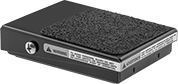 | 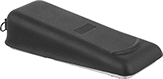 |
Back Pivot with 1 Pedal | Center Pivot with 1 Pedal |
Keep your hands free for other tasks by triggering switches with your foot.
2 Speeds—Two-speed switches have staged contacts. For slow speed, push the pedal halfway to close the first contact; for high speed, push it all the way to close the second contact.
Back—Back-pivot switches actuate with a tap of the toe.
Center—Center-pivot switches let you control two circuits with a single foot—one with your toe and one with your heel. Also known as rocker switches, they can be pressed either forward or backward, meaning you actuate one circuit at a time.
No. of Circuits Controlled | Switch Starting Position | Switch Action | Switch Designation | Switching Current @ Voltage | Housing Material | Wire Connection | No. of Terminals | Each | |||
|---|---|---|---|---|---|---|---|---|---|---|---|
1 Speed | |||||||||||
Center Pivot with 1 Pedal | |||||||||||
| 2 | 1 Off or 1 On | Momentary | SPDT | 15 amp @ 125V AC, 250V AC, 0.5 amp @ 125V DC, 0.25 amp @ 250V DC | Aluminum | Tab | 6 | 5767N13 | 0000000 | ||
2 Speeds | |||||||||||
Back Pivot with 1 Pedal | |||||||||||
| 1 | 1 Off or 1 On | Momentary | SPDT | 10 amp @ 125V AC, 250V AC, 0.5 amp @ 125V DC, 0.25 amp @ 250V DC | Aluminum | Tab | 6 | 5767N12 | 000000 | ||
Magnetic Contact Alarm Switches
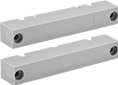 | 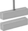 | 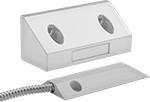 |
Style A with Screw Terminals | Style A with Wire Leads | Style B |
Wire contacts to an alarm system to alert when doors or windows are opened. Mount the magnet to the door or window and mount the switch to the frame. The alarm will activate when the magnet is pulled away by the opening door or window.
SPDT—SPDT switches connect to an alarm system and to another device, such as a motion detector.
Style | No. of Circuits Controlled | Switch Starting Position | Switch Designation | Switching Current @ Voltage | Max. Sensing Distance | Wire Lead Lg., ft. | Lg. | Wd. | Ht. | Color | Environment | Enclosure Rating | Each | |||
|---|---|---|---|---|---|---|---|---|---|---|---|---|---|---|---|---|
Plastic Housing with Screw Terminals | ||||||||||||||||
Screw On with Sealed Housing | ||||||||||||||||
| A | 1 | 1 Off or 1 On | SPDT | 0.25 amp @ 30V AC/30V DC | 0.75" | — | 2.5" | 0.56" | 0.5" | White | — | — | 8039A47 | 000000 | ||
| A | 1 | 1 Off or 1 On | SPDT | 0.25 amp @ 30V AC/30V DC | 1.25" | — | 3.93" | 0.75" | 0.62" | White | — | — | 8073A28 | 00000 | ||
Aluminum Housing with Wire Leads | ||||||||||||||||
Screw On with Flexible Stainless Steel Conduit and Sealed Housing | ||||||||||||||||
| A | 1 | 1 Off or 1 On | SPDT | 0.25 amp @ 30V AC/30V DC | 3" | 3 | 3" | 0.5" | 1" | — | Corrosive, Dusty, Oily, Outdoor, Submersible, Washdown, Wet | NEMA 4X, NEMA 6, NEMA 12, IP67 | 8039A52 | 000000 | ||
| B | 1 | 1 Off or 1 On | SPDT | 0.25 amp @ 30V AC/30V DC | 3" | 3 | 3.5" | 1.5" | 1.5" | — | Corrosive, Dusty, Oily, Outdoor, Submersible, Washdown, Wet | NEMA 4X, NEMA 6, NEMA 12, IP67 | 8135A32 | 00000 | ||
Pressure and Vacuum Transmitters with Digital Display
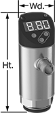
4 mA to 20 mA Output Signal—4-Pole M12 Plug-In Connection
 |
Max. Pressure, psi | Configurable Analog Transmitter/Digital Switch Output | Configurable Digital Switch Output | ||||||||||||||||||
|---|---|---|---|---|---|---|---|---|---|---|---|---|---|---|---|---|---|---|---|---|
Pressure Range, psi | Vacuum Range, in. Hg | Continuous | Short-Term | Input Voltage, V DC | Ht. | Wd. | No. Of | Analog Signal | Digital Signal | No. Of | Digital Signal | Measurement Unit | For Use With | Accuracy | Temp. Range, ° F | Connection Material | Each | |||
Glass-Filled Polyester Plastic Housing | ||||||||||||||||||||
1/4 NPT Female | ||||||||||||||||||||
| 0 to 14.5 | 0 to 29.5 | 145 | 145 | 18 to 30 | 3 9/16" | 1 3/8" | 1 | 4 mA to 20 mA | NPN, PNP | 1 | NPN, PNP | Inches of Mercury, Inches of Water, Kilopascals, Millibars, Pounds per Square Inch | Air, Argon, Diesel Fuel, Hydraulic Fluid, Nitrogen, Water | ±1% | -10 to 175 | 316L Stainless Steel | 4075N14 | 0000000 | ||
| 0 to 145 | 0 to 29.7 | 1,085 | 1,085 | 18 to 30 | 3 9/16" | 1 3/8" | 1 | 4 mA to 20 mA | NPN, PNP | 1 | NPN, PNP | Bar, Megapascals, Pounds per Square Inch | Air, Argon, Diesel Fuel, Hydraulic Fluid, Nitrogen, Water | ±1% | -10 to 175 | 316L Stainless Steel | 4075N15 | 000000 | ||
| 0 to 362.5 | 0 to 29.5 | 2,175 | 2,175 | 18 to 30 | 3 9/16" | 1 3/8" | 1 | 4 mA to 20 mA | NPN, PNP | 1 | NPN, PNP | Bar, Megapascals, Pounds per Square Inch | Air, Argon, Diesel Fuel, Hydraulic Fluid, Nitrogen, Water | ±1% | -10 to 175 | 316L Stainless Steel | 4075N16 | 000000 | ||
1/4 NPT Male | ||||||||||||||||||||
| 0 to 14.5 | 0 to 29.5 | 145 | 145 | 18 to 30 | 3 9/16" | 1 3/8" | 1 | 4 mA to 20 mA | NPN, PNP | 1 | NPN, PNP | Inches of Mercury, Inches of Water, Kilopascals, Millibars, Pounds per Square Inch | Air, Argon, Diesel Fuel, Hydraulic Fluid, Nitrogen, Water | ±1% | -10 to 175 | 316L Stainless Steel | 4075N11 | 000000 | ||
| 0 to 145 | 0 to 29.7 | 1,085 | 1,085 | 18 to 30 | 3 9/16" | 1 3/8" | 1 | 4 mA to 20 mA | NPN, PNP | 1 | NPN, PNP | Bar, Megapascals, Pounds per Square Inch | Air, Argon, Diesel Fuel, Hydraulic Fluid, Nitrogen, Water | ±1% | -10 to 175 | 316L Stainless Steel | 4075N12 | 000000 | ||
| 0 to 360 | 0 to 29.5 | 2,175 | 2,175 | 18 to 30 | 3 9/16" | 1 3/8" | 1 | 4 mA to 20 mA | NPN, PNP | 1 | NPN, PNP | Bar, Megapascals, Pounds per Square Inch | Air, Argon, Diesel Fuel, Hydraulic Fluid, Nitrogen, Water | ±1% | -10 to 175 | 316L Stainless Steel | 4075N13 | 000000 | ||
1/4 BSPP Female | ||||||||||||||||||||
| 0 to 7.3 | 0 to 14.8 | 145 | 145 | 18 to 30 | 3 9/16" | 1 3/8" | 1 | 4 mA to 20 mA | NPN, PNP | 1 | NPN, PNP | Inches of Water, Kilopascals, Millibars, Pounds per Square Inch | Air, Argon, Diesel Fuel, Hydraulic Fluid, Nitrogen, Water | ±1% | -10 to 175 | 316L Stainless Steel | 4075N23 | 000000 | ||
| 0 to 14.5 | 0 to 1.4 | 145 | 145 | 18 to 30 | 3 9/16" | 1 3/8" | 1 | 4 mA to 20 mA | NPN, PNP | 1 | NPN, PNP | Inches of Water, Kilopascals, Millibars, Pounds per Square Inch | Air, Argon, Diesel Fuel, Hydraulic Fluid, Nitrogen, Water | ±1% | -10 to 175 | 316L Stainless Steel | 4075N22 | 000000 | ||
| 0 to 14.5 | 0 to 29.5 | 145 | 145 | 18 to 30 | 3 9/16" | 1 3/8" | 1 | 4 mA to 20 mA | NPN, PNP | 1 | NPN, PNP | Inches of Mercury, Inches of Water, Kilopascals, Millibars, Pounds per Square Inch | Air, Argon, Diesel Fuel, Hydraulic Fluid, Nitrogen, Water | ±1% | -10 to 175 | 316L Stainless Steel | 4075N21 | 000000 | ||
| 0 to 87 | 0 to 29.5 | 600 | 600 | 18 to 30 | 3 9/16" | 1 3/8" | 1 | 4 mA to 20 mA | NPN, PNP | 1 | NPN, PNP | Bar, Megapascals, Pounds per Square Inch | Air, Argon, Diesel Fuel, Hydraulic Fluid, Nitrogen, Water | ±1% | -10 to 175 | 316L Stainless Steel | 4075N17 | 000000 | ||
| 0 to 145 | 0 to 29.7 | 1,085 | 1,085 | 18 to 30 | 3 9/16" | 1 3/8" | 1 | 4 mA to 20 mA | NPN, PNP | 1 | NPN, PNP | Bar, Megapascals, Pounds per Square Inch | Air, Argon, Diesel Fuel, Hydraulic Fluid, Nitrogen, Water | ±1% | -10 to 175 | 316L Stainless Steel | 4075N18 | 000000 | ||
| 0 to 360 | 0 to 29.5 | 2,175 | 2,175 | 18 to 30 | 3 9/16" | 1 3/8" | 1 | 4 mA to 20 mA | NPN, PNP | 1 | NPN, PNP | Bar, Megapascals, Pounds per Square Inch | Air, Argon, Diesel Fuel, Hydraulic Fluid, Nitrogen, Water | ±1% | -10 to 175 | 316L Stainless Steel | 4075N19 | 000000 | ||
1/4 BSPP Male | ||||||||||||||||||||
| 0 to 7.3 | 0 to 14.8 | 145 | 145 | 18 to 30 | 3 11/16" | 1 3/8" | 1 | 4 mA to 20 mA | NPN, PNP | 1 | NPN, PNP | Bar, Megapascals, Pounds per Square Inch | Air, Argon, Diesel Fuel, Hydraulic Fluid, Nitrogen, Water | ±1% | -10 to 175 | 316L Stainless Steel | 4075N27 | 000000 | ||
| 0 to 14.5 | 0 to 1.4 | 145 | 145 | 18 to 30 | 3 11/16" | 1 3/8" | 1 | 4 mA to 20 mA | NPN, PNP | 1 | NPN, PNP | Bar, Megapascals, Pounds per Square Inch | Air, Argon, Diesel Fuel, Hydraulic Fluid, Nitrogen, Water | ±1% | -10 to 175 | 316L Stainless Steel | 4075N28 | 000000 | ||
| 0 to 14.5 | 0 to 29.5 | 145 | 145 | 18 to 30 | 3 11/16" | 1 3/8" | 1 | 4 mA to 20 mA | NPN, PNP | 1 | NPN, PNP | Inches of Mercury, Inches of Water, Kilopascals, Millibars, Pounds per Square Inch | Air, Argon, Diesel Fuel, Hydraulic Fluid, Nitrogen, Water | ±1% | -10 to 175 | 316L Stainless Steel | 4075N29 | 000000 | ||
| 0 to 87 | 0 to 29.5 | 600 | 600 | 18 to 30 | 3 11/16" | 1 3/8" | 1 | 4 mA to 20 mA | NPN, PNP | 1 | NPN, PNP | Bar, Megapascals, Pounds per Square Inch | Air, Argon, Diesel Fuel, Hydraulic Fluid, Nitrogen, Water | ±1% | -10 to 175 | 316L Stainless Steel | 4075N24 | 000000 | ||
| 0 to 145 | 0 to 29.7 | 1,085 | 1,085 | 18 to 30 | 3 11/16" | 1 3/8" | 1 | 4 mA to 20 mA | NPN, PNP | 1 | NPN, PNP | Bar, Megapascals, Pounds per Square Inch | Air, Argon, Diesel Fuel, Hydraulic Fluid, Nitrogen, Water | ±1% | -10 to 175 | 316L Stainless Steel | 4075N25 | 000000 | ||
| 0 to 360 | 0 to 29.5 | 145 | 145 | 18 to 30 | 3 11/16" | 1 3/8" | 1 | 4 mA to 20 mA | NPN, PNP | 1 | NPN, PNP | Bar, Megapascals, Pounds per Square Inch | Air, Argon, Diesel Fuel, Hydraulic Fluid, Nitrogen, Water | ±1% | -10 to 175 | 316L Stainless Steel | 4075N26 | 000000 | ||
Insertion-Mount Flow and Temperature Transmitters
 |
 |
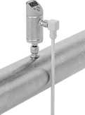
Thread mounting hardware (sold separately) into your pipe connection and insert the probe of these transmitters to measure the flow and temperature of water, oil, or air. The probe is held in place with a compression fitting on the other end of the mounting hardware. They’re often used in large-diameter pipes where it would be difficult to install a transmitter inline. To calculate the flow rate, these transmitters generate a small amount of heat, then measure the cooling effect your liquid or air has on it. They measure and output both flow and temperature, making them ideal for applications where temperature fluctuates. Also known as transducers, they convert measurements to an electrical signal that can be interpreted by receiving devices, such as remote displays and programmable logic controllers (PLCs) to monitor flow or control equipment. As flow or temperature increases, the output signal increases. For your receiving device to interpret the signal, you will need to calibrate it for the measurement range and output signal of the transmitter. They only give accurate readings within the rated measurement range. They’ll measure flow correctly in any mounting orientation. These transmitters are calibrated with air, glycol solutions, oil, and water but can be recalibrated in the field for other liquids.
Adjust settings at the source using the digital display. These transmitters have two configurable outputs. One can be wired for flow or temperature as an analog output or a digital switch. The other one can be wired for flow as a digital switch, digital pulse output, or IO Link. Pulse outputs send flow data using spikes of voltage that match the input voltage of the transmitter. The higher the flow, the more pulses they send. To change settings and receive error messages remotely from your PLC or computer, you can program one of the outputs to use IO Link. You’ll need an IO Link controller (not included) to connect to your interface.
For the Manufacturer User Manual, click on a part number and select Product Detail.
Flow Measurement Type | Flow Range, gpm | Probe Lg. | End-to-End Lg. | Accuracy | Max. Pressure @ Temp. | Temp. Range, ° F | Input Voltage Range, V DC | Mounting Position | Field Recalibratable | Enclosure Rating | Each | |||
|---|---|---|---|---|---|---|---|---|---|---|---|---|---|---|
One Digital Switch/Pulse Output and One 4-20 mA Analog Transmitter/Digital Switch/Pulse Output—4-Pole M12 Connection Plug | ||||||||||||||
316 Stainless Steel/Polybutylene Body with 316 Stainless Steel Fitting | ||||||||||||||
| Thermal | 0.02 to 12 | 3 15/16" | 7 9/16" | ±10% | 725 psi @ 212° F | 0 to 212 | 18 to 30 | Any Angle | Yes | IP65, IP67 | 4426N101 | 0000000 | ||
| Thermal | 0.02 to 12 | 7 7/8" | 11 1/2" | ±10% | 725 psi @ 212° F | 0 to 212 | 18 to 30 | Any Angle | Yes | IP65, IP67 | 4426N102 | 000000 | ||

