


Filter by
Mount Type
Head Material
Maximum Spring Force
Minimum Spring Force
DFARS Specialty Metals
U.S.–Mexico–Canada Agreement (USMCA) Qualifying
Export Control Classification Number (ECCN)

Spring Locating Pins
 |  |
Zinc-Plated Steel Head | Acetal Head |
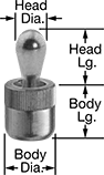
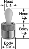
As the workpiece pushes against the pin head in one direction, the internal spring pushes back to hold it in place for clamping. Press into a drilled hole using the installation tool (sold separately). Also known as spring locating pins and side-thrust pins.
Acetal Head—Acetal-head pins won't mar soft metal and polished surfaces.
Pins | Installation Tools | |||||||||||||
|---|---|---|---|---|---|---|---|---|---|---|---|---|---|---|
Body | Head | |||||||||||||
Dia. | Lg. | Dia. | Lg. | Max. Head Movement | Min. Spring Force | Max. Spring Force, lbf | Body Dia. Tolerance | Body Material | Each | Each | ||||
Zinc-Plated Steel Head | ||||||||||||||
| 0.25" | 0.28" | 0.12" | 0.16" | 0.04" | 2.3 lbf | 2.5 | 0" to 0.0009" | Aluminum | 8485A51 | 00000 | 8485A81 | 000000 | ||
| 0.25" | 0.28" | 0.12" | 0.16" | 0.04" | 4.5 lbf | 5 | 0" to 0.0009" | Aluminum | 8485A52 | 0000 | 8485A81 | 00000 | ||
| 0.25" | 0.28" | 0.12" | 0.16" | 0.04" | Not Rated | 9 | -0.002" to 0.002" | Aluminum | 8485A88 | 0000 | 8485A81 | 00000 | ||
| 0.44" | 0.43" | 0.2" | 0.24" | 0.06" | 4.5 lbf | 5 | 0" to 0.0011" | Aluminum | 8485A53 | 0000 | 8485A82 | 00000 | ||
| 0.44" | 0.43" | 0.2" | 0.24" | 0.06" | 11.3 lbf | 12.4 | 0" to 0.0011" | Aluminum | 8485A54 | 0000 | 8485A82 | 00000 | ||
| 0.44" | 0.43" | 0.24" | 0.43" | 0.08" | 9 lbf | 9.9 | 0" to 0.0011" | Aluminum | 8485A55 | 0000 | 8485A82 | 00000 | ||
| 0.44" | 0.43" | 0.24" | 0.43" | 0.08" | 16.9 lbf | 18.6 | 0" to 0.0011" | Aluminum | 8485A56 | 0000 | 8485A82 | 00000 | ||
| 0.5" | 0.51" | 0.31" | 0.53" | 0.1" | 11.3 lbf | 12.4 | 0" to 0.0011" | Aluminum | 8485A57 | 0000 | 8485A83 | 00000 | ||
| 0.5" | 0.51" | 0.31" | 0.53" | 0.1" | 22.5 lbf | 24.8 | 0" to 0.0011" | Aluminum | 8485A58 | 0000 | 8485A83 | 00000 | ||
| 0.63" | 0.67" | 0.39" | 0.64" | 0.13" | 22.5 lbf | 24.8 | 0" to 0.0011" | Aluminum | 8485A59 | 0000 | 8485A84 | 00000 | ||
| 0.63" | 0.67" | 0.39" | 0.64" | 0.13" | 45 lbf | 49.5 | 0" to 0.0011" | Aluminum | 8485A61 | 0000 | 8485A84 | 00000 | ||
| 6 mm | 7 mm | 3 mm | 4 mm | 1 mm | 2.3 lbf | 2.5 | 0 mm to 0.0221 mm | Aluminum | 8485A11 | 0000 | 8485A81 | 00000 | ||
| 6 mm | 7 mm | 3 mm | 4 mm | 1 mm | 4.5 lbf | 5 | 0 mm to 0.0221 mm | Aluminum | 8485A12 | 0000 | 8485A81 | 00000 | ||
| 6 mm | 7 mm | 3 mm | 4 mm | 1 mm | 9 lbf | 9.9 | 0 mm to 0.0221 mm | Aluminum | 8485A41 | 0000 | 8485A81 | 00000 | ||
| 10 mm | 11 mm | 5 mm | 6.7 mm | 1.6 mm | 4.5 lbf | 5 | 0 mm to 0.0269 mm | Aluminum | 8485A13 | 0000 | 8485A82 | 00000 | ||
| 10 mm | 11 mm | 5 mm | 6.7 mm | 1.6 mm | 11.3 lbf | 12.4 | 0 mm to 0.0269 mm | Aluminum | 8485A14 | 0000 | 8485A82 | 00000 | ||
| 10 mm | 11 mm | 5 mm | 6.7 mm | 1.6 mm | 22.5 lbf | 24.8 | 0 mm to 0.0269 mm | Aluminum | 8485A42 | 0000 | 8485A82 | 00000 | ||
| 10 mm | 11 mm | 6 mm | 10.7 mm | 2 mm | 9 lbf | 9.9 | 0 mm to 0.0269 mm | Aluminum | 8485A15 | 0000 | 8485A82 | 00000 | ||
| 10 mm | 11 mm | 6 mm | 10.7 mm | 2 mm | 16.9 lbf | 18.6 | 0 mm to 0.0269 mm | Aluminum | 8485A16 | 0000 | 8485A82 | 00000 | ||
| 10 mm | 11 mm | 6 mm | 10.7 mm | 2 mm | 33.8 lbf | 37.1 | 0 mm to 0.0269 mm | Aluminum | 8485A43 | 0000 | 8485A82 | 00000 | ||
| 12 mm | 13 mm | 8 mm | 13.9 mm | 2.6 mm | 11.3 lbf | 12.4 | 0 mm to 0.0269 mm | Aluminum | 8485A17 | 0000 | 8485A83 | 00000 | ||
| 12 mm | 13 mm | 8 mm | 13.9 mm | 2.6 mm | 22.5 lbf | 24.8 | 0 mm to 0.0269 mm | Aluminum | 8485A18 | 0000 | 8485A83 | 00000 | ||
| 16 mm | 17 mm | 10 mm | 16.7 mm | 3.2 mm | 22.5 lbf | 24.8 | 0 mm to 0.0269 mm | Aluminum | 8485A45 | 0000 | 8485A84 | 00000 | ||
| 16 mm | 17 mm | 10 mm | 16.7 mm | 3.2 mm | 67.5 lbf | 74.3 | 0 mm to 0.0269 mm | Aluminum | 8485A46 | 0000 | 8485A84 | 00000 | ||
Acetal Head | ||||||||||||||
| 0.25" | 0.28" | 0.12" | 0.16" | 0.04" | 2.3 lbf | 2.5 | 0" to 0.0009" | Aluminum | 1366N11 | 0000 | 8485A81 | 00000 | ||
| 0.44" | 0.38" | 0.24" | 0.41" | 0.08" | 13.5 lbf | 14.8 | 0" to 0.0011" | Aluminum | 1366N13 | 0000 | 8485A82 | 00000 | ||
| 0.44" | 0.43" | 0.24" | 0.43" | 0.08" | 9 lbf | 9.9 | 0" to 0.0011" | Aluminum | 1366N12 | 0000 | 8485A82 | 00000 | ||
| 0.5" | 0.51" | 0.31" | 0.53" | 0.1" | 11.3 lbf | 12.4 | 0" to 0.0011" | Aluminum | 1366N14 | 0000 | 8485A83 | 00000 | ||
| 0.63" | 0.67" | 0.39" | 0.64" | 0.13" | 22.5 lbf | 24.8 | 0" to 0.0011" | Aluminum | 1366N15 | 0000 | 8485A84 | 00000 | ||
| 6 mm | 7 mm | 3 mm | 4 mm | 1 mm | 2.3 lbf | 2.5 | 0 mm to 0.022 mm | Aluminum | 1366N21 | 0000 | 8485A81 | 00000 | ||
| 10 mm | 11 mm | 5 mm | 6.7 mm | 1.6 mm | 4.5 lbf | 5 | 0 mm to 0.027 mm | Aluminum | 1366N22 | 0000 | 8485A82 | 00000 | ||
| 10 mm | 11 mm | 6 mm | 10.7 mm | 2 mm | 9 lbf | 9.9 | 0 mm to 0.027 mm | Aluminum | 1366N23 | 0000 | 8485A82 | 00000 | ||
| 12 mm | 13 mm | 8 mm | 13.9 mm | 2.6 mm | 11.3 lbf | 12.4 | 0 mm to 0.027 mm | Aluminum | 1366N24 | 0000 | 8485A83 | 00000 | ||
| 16 mm | 17 mm | 10 mm | 16.7 mm | 3.2 mm | 22.5 lbf | 24.8 | 0 mm to 0.027 mm | Aluminum | 1366N25 | 0000 | 8485A84 | 00000 | ||
Spring Locating Pin Installation Tools


Threaded Spring Locating Pins
 |
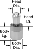
Threading makes these guide pins easier to remove and replace than press fit, so they're useful for high-wear applications. A sealed top prevents debris from getting inside and making them seize up. As the workpiece pushes against the pin head in one direction, the internal spring pushes back to hold it in place for clamping.
Pins | Installation Tools | ||||||||||||||
|---|---|---|---|---|---|---|---|---|---|---|---|---|---|---|---|
Body, mm | Head, mm | ||||||||||||||
Thread Size | Dia. | Lg. | Dia. | Lg. | Max. Head Movement, mm | Min. Spring Force | Max. Spring Force, lbf | Body Dia. Tolerance, mm | Body Material | Each | Each | ||||
Zinc-Plated Steel Head | |||||||||||||||
| M12 × 1.75 mm | 10 | 11.5 | 5 | 6 | 0.8 | Not Rated | 4.5 | -0.15 to 0.15 | Steel | 3077N11 | 00000 | 8485A93 | 000000 | ||
| M12 × 1.75 mm | 10 | 11.5 | 5 | 6 | 0.8 | Not Rated | 22 | -0.15 to 0.15 | Steel | 3077N14 | 0000 | 8485A93 | 00000 | ||
| M12 × 1.75 mm | 10 | 11.5 | 6 | 10 | 1 | Not Rated | 9 | -0.15 to 0.15 | Steel | 3077N12 | 0000 | 8485A93 | 00000 | ||
| M12 × 1.75 mm | 10 | 11.5 | 6 | 10 | 1 | Not Rated | 16 | -0.15 to 0.15 | Steel | 3077N13 | 0000 | 8485A93 | 00000 | ||
| M18 × 1.5 mm | 16 | 18 | 10 | 16 | 1.6 | Not Rated | 33 | -0.15 to 0.15 | Steel | 3077N15 | 0000 | 8485A94 | 00000 | ||
| M18 × 1.5 mm | 16 | 18 | 10 | 16 | 1.6 | Not Rated | 45 | -0.15 to 0.15 | Steel | 3077N16 | 0000 | 8485A94 | 00000 | ||
Sealed Spring Locating Pins
 |
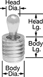
Sealed at the top to prevent debris from getting inside and making them seize up, these guide pins are a good choice for machining fixtures. As the workpiece pushes against the pin head in one direction, the internal spring pushes back to hold it in place for clamping. Press into a drilled hole using the installation tool (sold separately).
Stainless Steel Head—Stainless steel pins are a good choice to avoid corrosion when working with stainless steel workpieces or fixtures.
Pins | Installation Tools | |||||||||||||
|---|---|---|---|---|---|---|---|---|---|---|---|---|---|---|
Body | Head | |||||||||||||
Dia. | Lg. | Dia. | Lg. | Max. Head Movement | Max. Spring Force, lbf | Body Dia. Min. Tolerance | Body Dia. Max. Tolerance | Body Material | Each | Each | ||||
Zinc-Plated Steel Head | ||||||||||||||
| 0.5" | 0.52" | 0.32" | 0.51" | 0.05" | 11 | 0.000" | 0.001" | Aluminum | 3074N21 | 000000 | 8485A83 | 000000 | ||
Stainless Steel Head | ||||||||||||||
| 0.25" | 0.28" | 0.12" | 0.16" | 0.02" | 4.5 | — | 0.004" | Aluminum | 3074N16 | 0000 | 8485A81 | 00000 | ||
| 0.44" | 0.37" | 0.24" | 0.41" | 0.04" | 6.7 | -0.0004" | 0.0004" | Aluminum | 3074N17 | 00000 | 8485A82 | 00000 | ||
| 0.63" | 0.68" | 0.39" | 0.68" | 0.06" | 18 | -0.0004" | 0.0004" | Aluminum | 3074N19 | 00000 | 8485A84 | 00000 | ||
Create-Your-Own Spring Locating Pins
 |
Thread in a screw, handle, or other part to create the right size and shape guide pin for your application. As the workpiece pushes against the pin head in one direction, the internal spring pushes back to hold it in place for clamping. Press into a drilled hole using the installation tool (sold separately).
