


Filter by
System of Measurement
Fitting Connection

For Use With
Body Material
Disc Material
Handle Style
Seat Material
Maximum Pressure @ Temperature
Bolt Circle Diameter
Bolt Diameter
Connects To
Maximum Temperature
DFARS Specialty Metals
Export Control Classification Number (ECCN)
Flanged Flow-Adjustment Valves
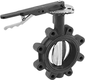
Wafer Valves with Lockable Lever Handle
 |  |
4 Bolt Holes | 8 Bolt Holes |
Wafer valves must be sandwiched between two flanges; they have tabs or unthreaded holes to help align the valve between the flanges.
Lockable lever handles can be fixed in place with a padlock (not included).
Flow Coefficient (Cv)—Flow coefficient (Cv) is the amount of water (in gallons per minute) at 60° F that will flow through a fully open valve with a difference of 1 psi between the inlet and the outlet.
Pipe Size | For Max. Shackle Dia. | For Use With | Pressure Class | Flange OD | Bolt Circle Dia. | No. of Bolt Holes | Bolt Hole Size | Bolts Included | Flow Coefficient (Cv) | Max. Pressure @ Temp. | Temp. Range, ° F | End-to-End Lg. | Specs. Met | Valve Type | Each | |||
|---|---|---|---|---|---|---|---|---|---|---|---|---|---|---|---|---|---|---|
Ductile Iron Body—Painted Ductile Iron Disc | ||||||||||||||||||
| 5 | 5/16" | Air | 125, 150 | 10" | 8 1/2" | 4 | 3/4" | No | 1,022 | 200 psi @ 180° F | 10 to 180 | 2 3/8" | MSS SP-67 | Butterfly | 5158K252 | 0000000 | ||
| 5 | 5/16" | Air | 125, 150 | 10" | 8 1/2" | 4 | 3/4" | No | 1,022 | 200 psi @ 275° F | -30 to 275 | 2 3/8" | MSS SP-67 | Butterfly | 5158K152 | 000000 | ||
Ductile Iron Body—Ductile Iron Disc | ||||||||||||||||||
| 5 | 1/4" | Water | 125, 150 | 10" | 8 1/2" | 8 | 3/4" | No | Not Rated | 250 psi @ 180° F | -20 to 180 | 2 5/16" | API Std 609, MSS SP-67 | Butterfly | 5024K22 | 000000 | ||
| 5 | 1/4" | Water | 125, 150 | 10" | 8 1/2" | 8 | 3/4" | No | Not Rated | 250 psi @ 225° F | -20 to 225 | 2 5/16" | API Std 609, MSS SP-67 | Butterfly | 5024K615 | 000000 | ||
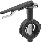
Lug Valves with Lockable Lever Handle
 |
8 Bolt Holes |
Lug valves can be sandwiched between two flanges or bolted directly to a single flange for servicing one end of the pipeline without depressurizing the other side. They have threaded flange holes with a hole pattern that matches ANSI flanges of the same pipe size.
Lockable lever handles can be fixed in place with a padlock (not included).
Flow Coefficient (Cv)—Flow coefficient (Cv) is the amount of water (in gallons per minute) at 60° F that will flow through a fully open valve with a difference of 1 psi between the inlet and the outlet.
Pipe Size | For Max. Shackle Dia. | For Use With | Pressure Class | Flange OD | Bolt Circle Dia. | No. of Bolt Holes | Bolt Hole Size | Bolts Included | Flow Coefficient (Cv) | Max. Pressure @ Temp. | Temp. Range, ° F | End-to-End Lg. | Specs. Met | Valve Type | Each | |||
|---|---|---|---|---|---|---|---|---|---|---|---|---|---|---|---|---|---|---|
Ductile Iron Body—Painted Ductile Iron Disc | ||||||||||||||||||
| 5 | 5/16" | Air | 125, 150 | 10" | 8 1/2" | 8 | 3/4" | No | 1,022 | 200 psi @ 180° F | 10 to 180 | 2 1/4" | MSS SP-67 | Butterfly | 5158K652 | 0000000 | ||
| 5 | 5/16" | Air | 125, 150 | 10" | 8 1/2" | 8 | 3/4" | No | 1,022 | 200 psi @ 275° F | -30 to 275 | 2 1/4" | MSS SP-67 | Butterfly | 5158K552 | 000000 | ||
Ductile Iron Body—Ductile Iron Disc | ||||||||||||||||||
| 5 | 1/4" | Water | 125, 150 | 10" | 8 1/2" | 8 | 3/4" | No | Not Rated | 250 psi @ 225° F | -20 to 225 | 2 5/16" | API Std 609, MSS SP-67 | Butterfly | 5024K662 | 000000 | ||
| 5 | 1/4" | Oil | 125, 150 | 10" | 8 1/2" | 8 | 3/4" | No | Not Rated | 250 psi @ 180° F | -20 to 180 | 2 5/16" | API Std 609, MSS SP-67 | Butterfly | 5024K68 | 000000 | ||
Flanged Flow-Adjustment Valves for Chemicals
Wafer Valves with Lockable Lever Handle
 | 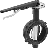 |
4 Bolt Holes | 8 Bolt Holes |
Wafer valves must be sandwiched between two flanges; they have tabs or unthreaded holes to help align the valve between the flanges.
Lockable lever handles have 10 flow-adjustment positions. The handle can be fixed in place with a padlock (not included).
Flow Coefficient (Cv)—Flow coefficient (Cv) is the amount of water (in gallons per minute) at 60° F that will flow through a fully open valve with a difference of 1 psi between the inlet and the outlet.
Pipe Size | For Use With | For Max. Shackle Dia. | Pressure Class | Flange OD | Bolt Circle Dia. | No. of Bolt Holes | Bolt Hole Size | Bolts Included | Flow Coefficient (Cv) | Max. Pressure @ Temp. | Temp. Range, ° F | End-to-End Lg. | Valve Type | Seat Material | Specs. Met | Each | |||
|---|---|---|---|---|---|---|---|---|---|---|---|---|---|---|---|---|---|---|---|
Ductile Iron Body—Painted Ductile Iron Disc | |||||||||||||||||||
| 5 | Air, Carbon Dioxide, Diesel Fuel, Isopropyl Alcohol, Methyl Ethyl Ketone (MEK), Nitrogen, Oxygen, Toluene (Methylbenzene) | 5/16" | 125, 150 | 10" | 8 1/2" | 4 | 7/8" | No | 1,022 | 200 psi @ 275° F | 10 to 275 | 2 1/4" | Butterfly | Fluoroelastomer | MSS SP-67 | 46165K105 | 000000000 | ||
Ductile Iron Body—316 Stainless Steel Disc | |||||||||||||||||||
| 5 | Carbon Dioxide, Gasoline, Liquid Carbon Dioxide, Phosphoric Acid | 1/4" | 125, 150 | 10" | 8 1/2" | 8 | 7/8" | No | Not Rated | 250 psi @ 210° F | -20 to 210 | 2 5/16" | Butterfly | Fluoroelastomer | API Std 609, MSS SP-67 | 5024K28 | 00000000 | ||
Lug Valves with Lockable Lever Handle
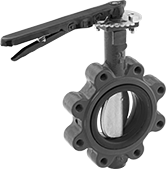 |
8 Bolt Holes |
Lug valves can be sandwiched between two flanges or bolted directly to a single flange for servicing one end of the pipeline without depressurizing the other side. They have threaded flange holes with a hole pattern that matches ANSI flanges of the same pipe size.
Lockable lever handles have 10 flow-adjustment positions. The handle can be fixed in place with a padlock (not included).
Flow Coefficient (Cv)—Flow coefficient (Cv) is the amount of water (in gallons per minute) at 60° F that will flow through a fully open valve with a difference of 1 psi between the inlet and the outlet.
Pipe Size | For Use With | For Max. Shackle Dia. | Pressure Class | Flange OD | Bolt Circle Dia. | No. of Bolt Holes | Bolt Hole Size | Bolts Included | Flow Coefficient (Cv) | Max. Pressure @ Temp. | Temp. Range, ° F | End-to-End Lg. | Valve Type | Seat Material | Specs. Met | Each | |||
|---|---|---|---|---|---|---|---|---|---|---|---|---|---|---|---|---|---|---|---|
Ductile Iron Body—Painted Ductile Iron Disc | |||||||||||||||||||
| 5 | Air, Carbon Dioxide, Diesel Fuel, Isopropyl Alcohol, Methyl Ethyl Ketone (MEK), Nitrogen, Oxygen, Toluene (Methylbenzene) | 5/16" | 125, 150 | 10" | 8 1/2" | 8 | 7/8" | No | 1,022 | 200 psi @ 275° F | 10 to 275 | 2 1/4" | Butterfly | Fluoroelastomer | MSS SP-67 | 46165K115 | 000000000 | ||
Ductile Iron Body—316 Stainless Steel Disc | |||||||||||||||||||
| 5 | Carbon Dioxide, Gasoline, Liquid Carbon Dioxide, Phosphoric Acid | 1/4" | 125, 150 | 10" | 8 1/2" | 8 | 7/8" | No | Not Rated | 250 psi @ 210° F | -20 to 210 | 2 5/16" | Butterfly | Fluoroelastomer | API Std 609, MSS SP-67 | 5024K75 | 00000000 | ||
Flanged Check Valves
Cast Iron Body
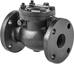 |
Flow Coefficient (Cv)—Flow coefficient (Cv) is the amount of water (in gallons per minute) at 60° F that will flow through a fully open valve with a difference of 1 psi between the inlet and the outlet.
Pipe Size | Flow Coefficient (Cv) | Max. Pressure @ Temp. | Max. Steam Pressure @ Temp. | Min. Opening Pressure, psi | Temp. Range, ° F | End-to-End Lg. | Mounting Position | Flange OD | No. of Bolt Holes | Bolt Hole Size | Bolt Circle Dia. | Bolts Included | Includes | Specs. Met | For Use With | Disc Material | Seal Material | Each | |||
|---|---|---|---|---|---|---|---|---|---|---|---|---|---|---|---|---|---|---|---|---|---|
Flanged × Flanged—Pressure Class 125 | |||||||||||||||||||||
| 5 | 735 | 200 psi @ 70° F | 125 psi @ 353° F | 1 | -20 to 405 | 13" | Horizontal | 10" | 8 | 3/4" | 8 1/2" | No | Removable Cap | ASTM A126 Class B, MSS SP-71 | Air, Steam, Water | Iron | Bronze | 8200T15 | 000000000 | ||
Flange-Mount Check Valves
Cast Iron Body
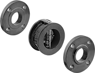 | 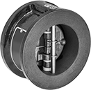 |
Shown with Flanges (Not Included) |
Flow Coefficient (Cv)—Flow coefficient (Cv) is the amount of water (in gallons per minute) at 60° F that will flow through a fully open valve with a difference of 1 psi between the inlet and the outlet.
Pipe Size | Flow Coefficient (Cv) | Max. Pressure @ Temp. | Min. Opening Pressure, psi | Temp. Range, ° F | End-to-End Lg. | Mounting Position | For Flange Class | For Use With | Disc Material | Seal Material | Each | |||
|---|---|---|---|---|---|---|---|---|---|---|---|---|---|---|
Flanged × Flanged | ||||||||||||||
| 5 | 520 | 200 psi @ 70° F | 1.25 | -20 to 250 | 2 3/4" | Horizontal, Vertical | 125 | Air, Argon, Helium, Krypton, Neon, Water, Xenon | Bronze | Buna-N | 5023K45 | 0000000 | ||
